Tensioner For Flexible Drives

Active Publication Date: 2010-09-16
LITENS AUTOMOTIVE INC
View PDF23 Cites 26 Cited by
  • Summary
  • Abstract
  • Description
  • Claims
  • Application Information

AI Technical Summary

Benefits of technology

[0011]The present invention provides a tensioner which employs a spindle and a tensioner arm which are preferably manufactured by die casting or similar manufacturing techniques, negating a requirement for machining operations. The biasing spring of the tensioner preferably includes coils formed from wire having a non-circular cross section to increase the spring force of the spring compared to a similar spring with coils of wire having a

Problems solved by technology

While such tensioners are well known, they suffer from disadvantages in that they can be relatively large, requiring significant available mounting volume (package volume) on the engine or other device on which they are installed.
Further, while dampening the movement of the tensioner arm away from the flexible drive (the de-tensioning direction) to reduce oscillation is desired, dampening movement of the ten

Method used


Image

  • Tensioner For Flexible Drives
  • Tensioner For Flexible Drives
  • Tensioner For Flexible Drives

Examples


Embodiment Construction

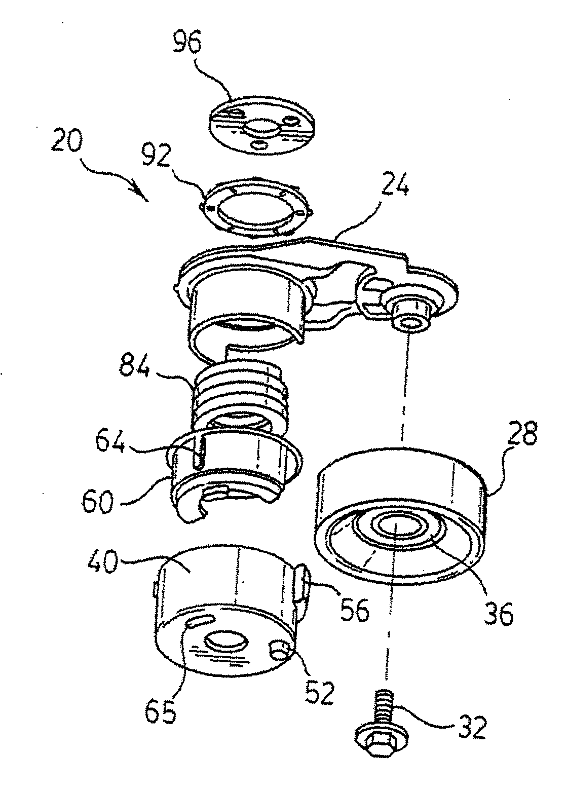
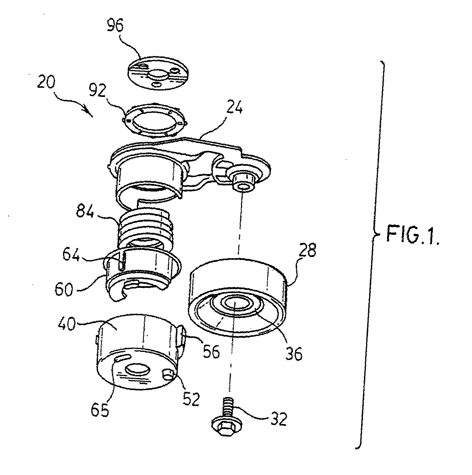
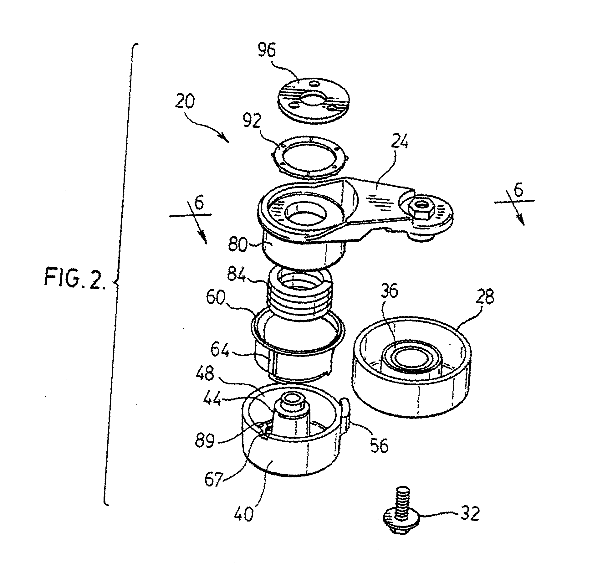
[0026]A tensioner for a flexible drive, in accordance with the present invention, is indicated generally at 20 in FIGS. 1, 2 and 6. Tensioner 20 comprises a tensioner arm 24 to which a pulley 28 is rotatably mounted via a bolt 32 and a bearing 36, defining a first axis of rotation. Bolt 32 engages a threaded fastener 33 formed in or attached to the tensioner arm 24 at one end thereof. Bearing 36 can be integrally formed in pulley 28 or can be a separate bearing installed on pulley 28. Pulley 28 can be designed to tension an endless rubber belt, either smooth or toothed, a chain or other flexible endless drive.

[0027]Tensioner 20 further includes a conical spindle 44 having a base comprising a spindle cup 40 and an outer radial wall 48, which is preferably somewhat conical in shape, as best seen in FIG. 6. Spindle cup 40 can include one or more index features or protrusions 52 on the outer bottom or mounting surface which engage complementary features on the engine or other surface to...


PUM


Abstract

A tensioner in accordance with the present invention employs a spindle and a tensioner arm which are preferably manufactured by a suitable manufacturing process, such as die casting, negating a requirement for machining operations. The biasing spring of the tensioner is wound with wire having a non-circular cross section to increase the spring force of the spring compared to a similar spring wound with wire of circular cross section and, as the tensioner arm is moved away from the flexible drive, the diameter of the biasing spring expands and the coils press a dampening shoe into contact with a wall of the tensioner arm producing a dampening force. The tensioner is simple to assemble and requires a relatively small package volume for the biasing force it can produce.

Description

FIELD OF THE INVENTION[0001]The present invention relates to tensioners for flexible drives. More specifically, the present invention relates to tensioners with a reduced package volume, reduced manufacturing costs and / or simplified assembly.BACKGROUND OF THE INVENTION[0002]Tensioners for flexible drive systems, and in particular for flexible drive systems comprising accessory drive systems on internal combustion engines, are well known. Such tensioners include a pulley which is biased toward the flexible drive, typically a rubber belt. The pulley is mounted to an arm which is biased towards the flexible drive (the tensioning direction) by a spring and the arm can also include means to produce a dampening force to inhibit oscillation of the arm and / or flexible drive.[0003]While such tensioners are well known, they suffer from disadvantages in that they can be relatively large, requiring significant available mounting volume (package volume) on the engine or other device on which the...

Claims


Application Information

Patent Timeline
IPC IPC(8): F16H7/12
CPCF16H7/1218F16H2007/084F16H2007/081F16H7/1281F16H7/08F16H7/12
Inventor ANTCHAK, JOHN R.DELL, JAMES W.HAMERS, GERALD J.LIU, FENG
Owner LITENS AUTOMOTIVE INC
Why Eureka
Try Eureka