Unlock instant, AI-driven research and patent intelligence for your innovation.

Heat exchange system

Inactive Publication Date: 2010-09-23
RENEWABLE RESOURCE RECOVERY
View PDF21 Cites 15 Cited by
  • Summary
  • Abstract
  • Description
  • Claims
  • Application Information

AI Technical Summary

Benefits of technology

[0005]There is therefore a need for a heat exchange system which addr

Problems solved by technology

However, the known heat pump systems have a number of disadvantages.

Method used


Image

  • Heat exchange system
  • Heat exchange system
  • Heat exchange system

Examples


Embodiment Construction

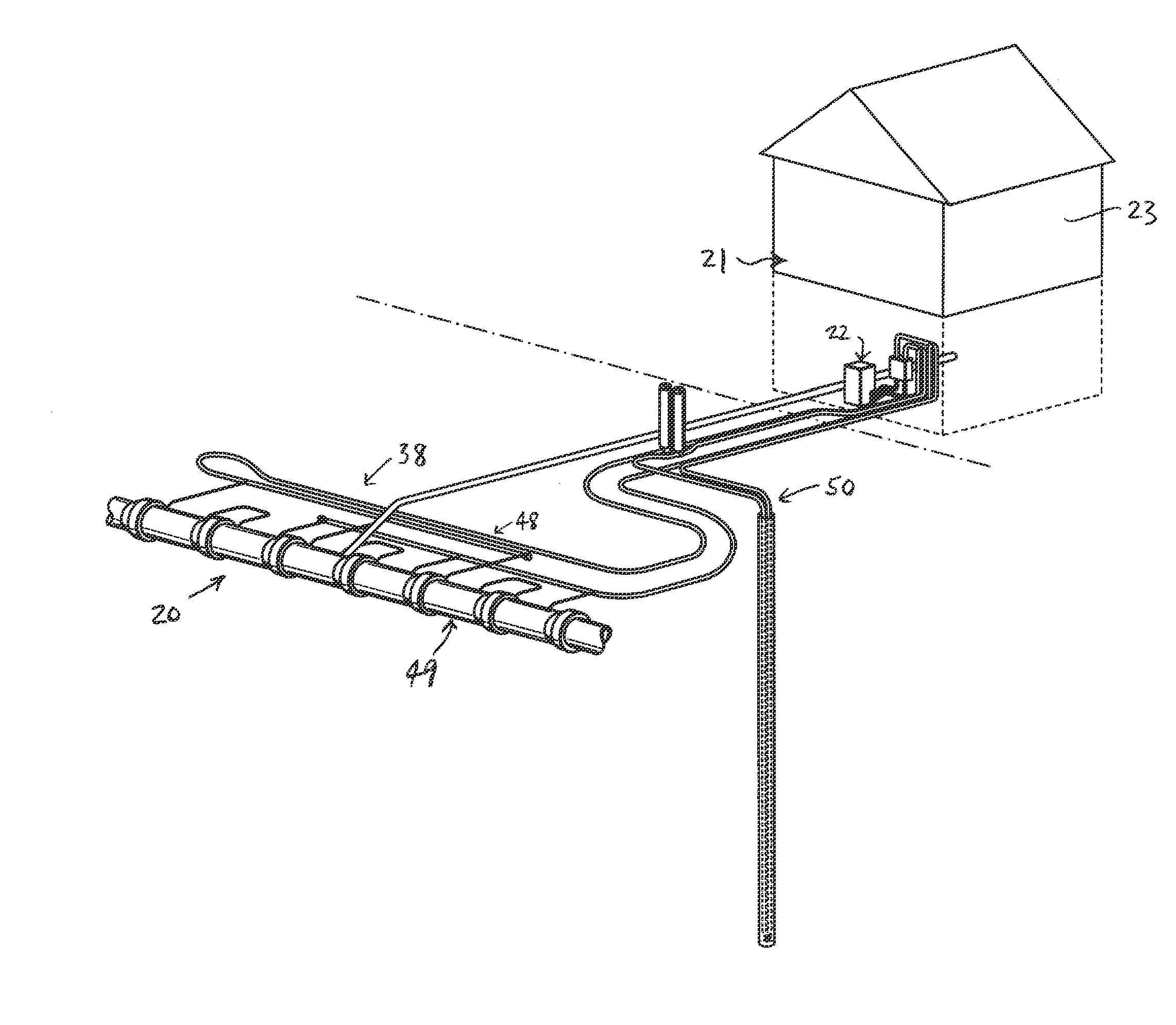
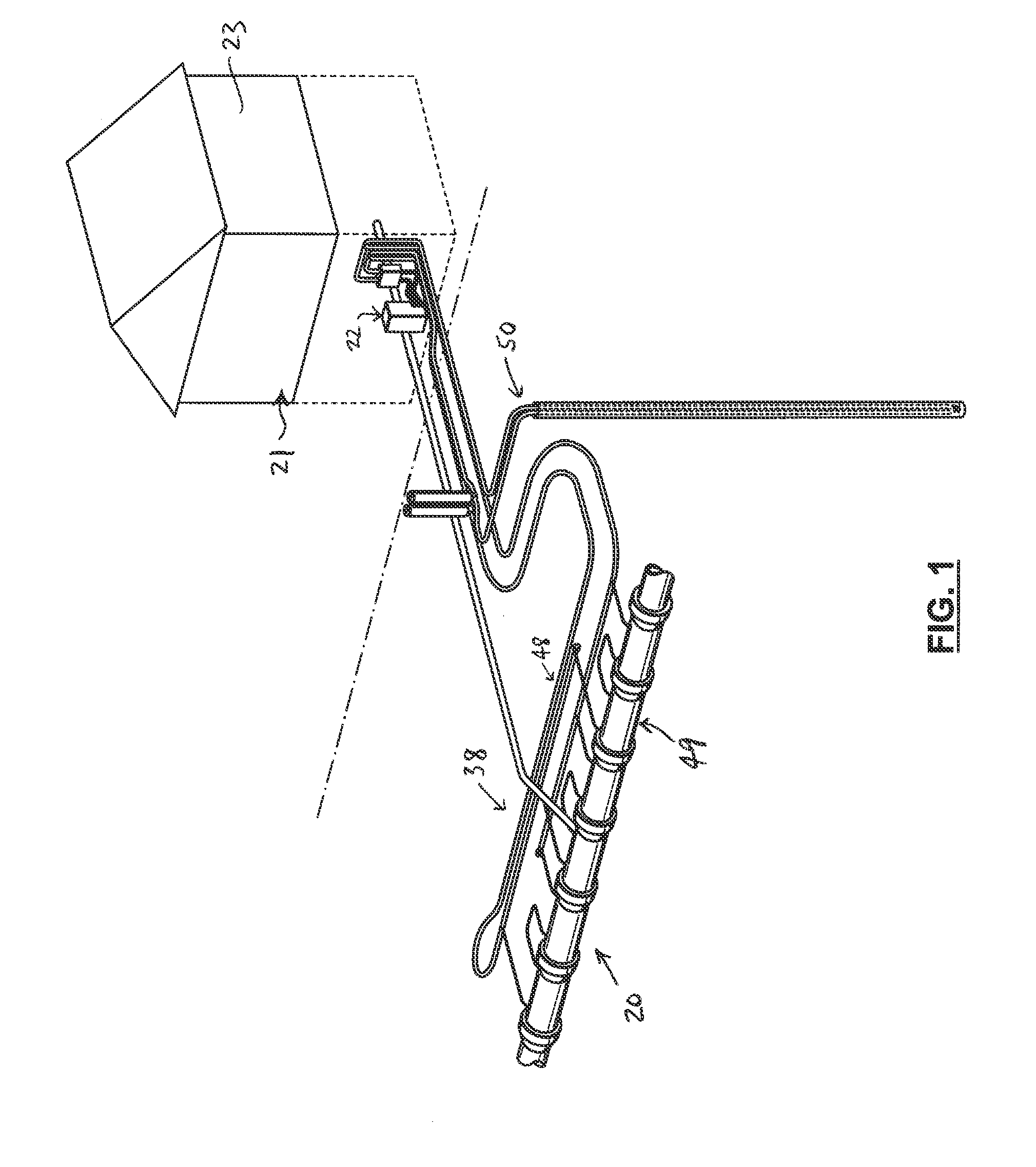
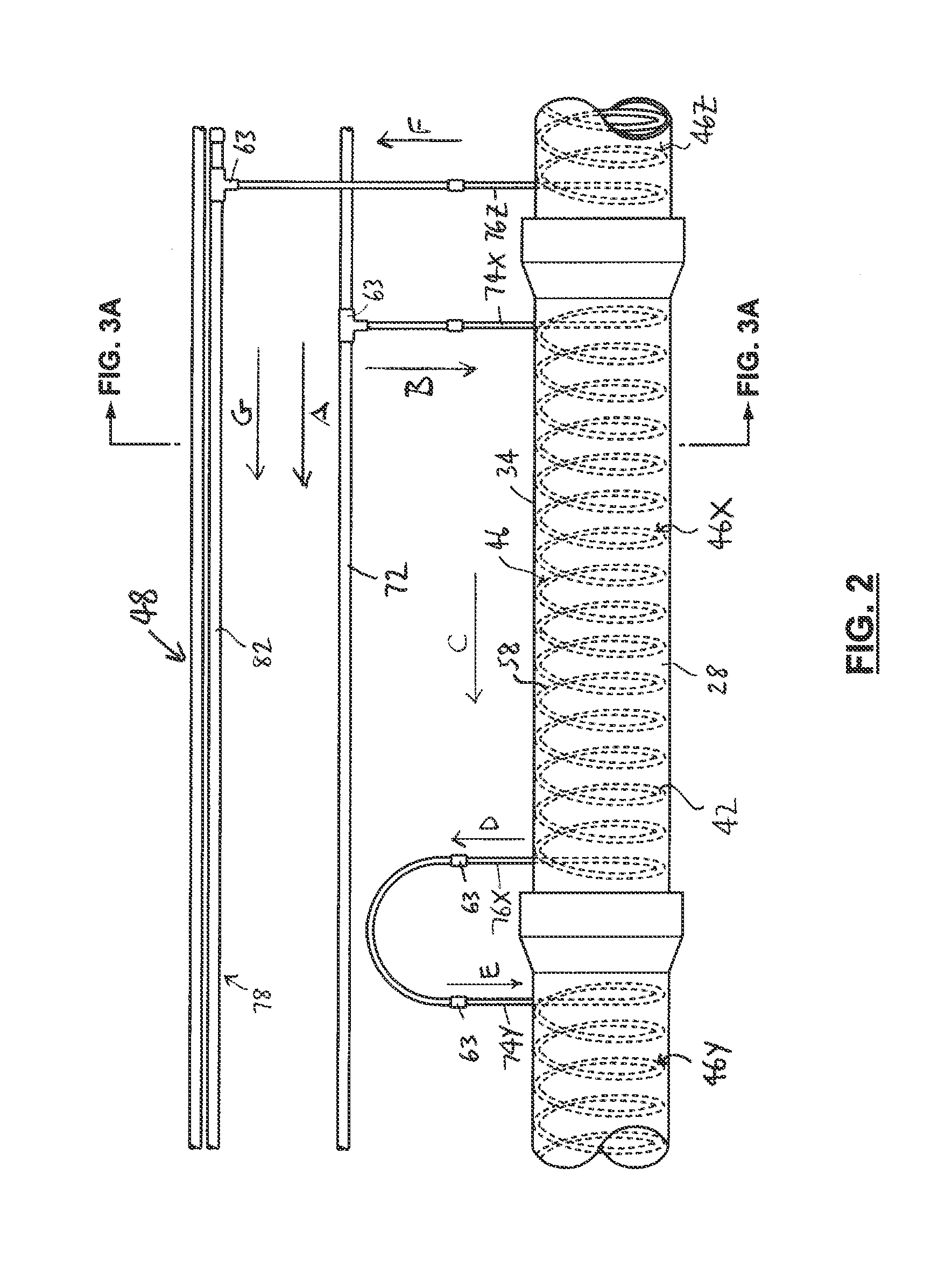
[0028]In the attached drawings, like reference numerals designate corresponding elements throughout. Reference is first made to FIGS. 1-5A to describe an embodiment of a heat exchange system 20 of the invention. In one embodiment, the heat exchange system 20 includes a heat pump assembly 22 for controlling an indoor fluid's temperature having a heat exchanger 24 with a heat exchange fluid 26 circulatable therein (FIG. 4). Preferably, the heat exchange system 20 includes one or more elongate pipe bodies 28, each pipe body 28 defining one or more conduits 30 therein in which one or more fluids 32 are receivable (FIGS. 2, 3B, 5A). Each pipe body 28 also includes an exterior surface 34 which is adapted for engagement with ground material 36. In one embodiment, the heat exchange system 20 preferably also includes one or more ground loop circuits 38 in fluid communication with one or more pumps 40 (FIG. 4), for circulating a heat transfer medium 42 through each ground loop circuit 38. As ...


PUM

PropertyMeasurementUnit
Temperatureaaaaaaaaaa
Pressureaaaaaaaaaa
Thermal conductivityaaaaaaaaaa

Abstract

A heat exchange system including a heat pump assembly for controlling an indoor fluid's temperature having a heat exchanger with a heat exchange fluid circulatable therein and one or more elongate pipe bodies defining one or more conduits therein in which a fluid is receivable. The system includes one or more ground loop circuits through which a heat transfer medium is circulated. The ground loop circuit includes one or more pipe portions at least partially engaged with the pipe body. The pipe portion is at least partially located proximal to the conduit for heat exchange between the fluid in the conduit and the heat exchange medium in the pipe portion, and the pipe portion is at least partially located proximal to the exterior surface for heat exchange between the ground material and the heat exchange medium in the pipe portion.

Description

[0001]This application claims the benefit of U.S. Provisional Patent Application No. 61 / 161,948, filed Mar. 20, 2009, and incorporates such provisional patent application in its entirety by reference.FIELD OF THE INVENTION[0002]The present invention is a heat exchange system including one or more pipe assemblies.BACKGROUND OF THE INVENTION[0003]Heat pumps, and in particular geothermal heat pumps, are well known in the art. In general, geothermal heat pumps are adapted to draw energy from shallow ground, i.e., energy from the sun which is stored in the ground. The shallow ground is used as a heat source (i.e., when the heat pump is used to provide heat to an indoor space in a building), or a heat sink (i.e., when the heat pump is operating to cool the indoor space), as is known.[0004]Various geothermal heat pump systems are known. However, the known heat pump systems have a number of disadvantages. In particular, only the shallow ground is used as a heat source or a heat sink, in the...

Claims


Application Information

Patent Timeline
IPC IPC(8): F24J3/08F28F1/00B23P15/26
CPCF25B30/06Y10T29/49391F24D2200/11F24D2200/12F24D2200/20Y02B10/40Y02B30/52Y02B10/70Y02B30/566Y02E10/125Y02E10/16F24J3/083F24J3/086F28D7/0016F28D7/024F28D21/0012E03C2001/005F24D17/0005F24T10/15Y02B30/18F24T10/10Y02B30/56Y02E10/10F28F27/02
Inventor NANEFF, BORIS P.MANCINI, ROBERTLISK, LESLIE J.HOOD, JOHN D.
Owner RENEWABLE RESOURCE RECOVERY