Improvements in/or relating to a method of treating sludges

a technology of sludge and belt, which is applied in the direction of liquefaction, solidification, light and heating apparatus, etc., can solve the problems of high specialised belts and power requirements

Inactive Publication Date: 2010-09-23
FDE PROCESS SYST
View PDF9 Cites 9 Cited by
  • Summary
  • Abstract
  • Description
  • Claims
  • Application Information

AI Technical Summary

Benefits of technology

[0008]It is therefore an object of the present invention to provide a method of treating sludges which will obviate or minimise the foregoing disadvantages in a simple yet effective manner or will at least provide the public with a useful choice.

Problems solved by technology

However significant electric power is required to drive such dewatering and the provision of highly specialised belts is also required.
As such the proposal is disadvantageous.

Method used


Image

  • Improvements in/or relating to a method of treating sludges
  • Improvements in/or relating to a method of treating sludges
  • Improvements in/or relating to a method of treating sludges

Examples


Embodiment Construction

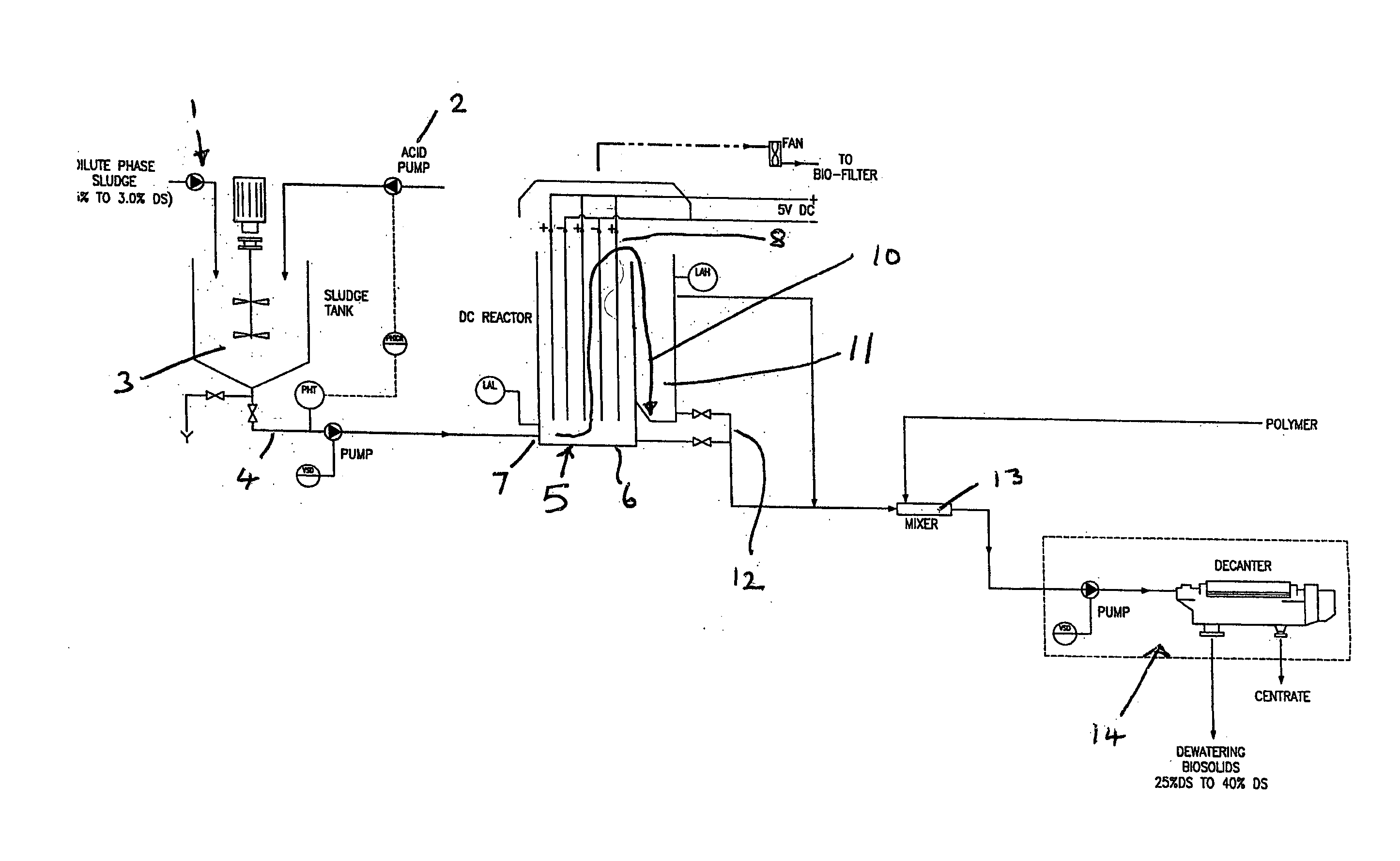
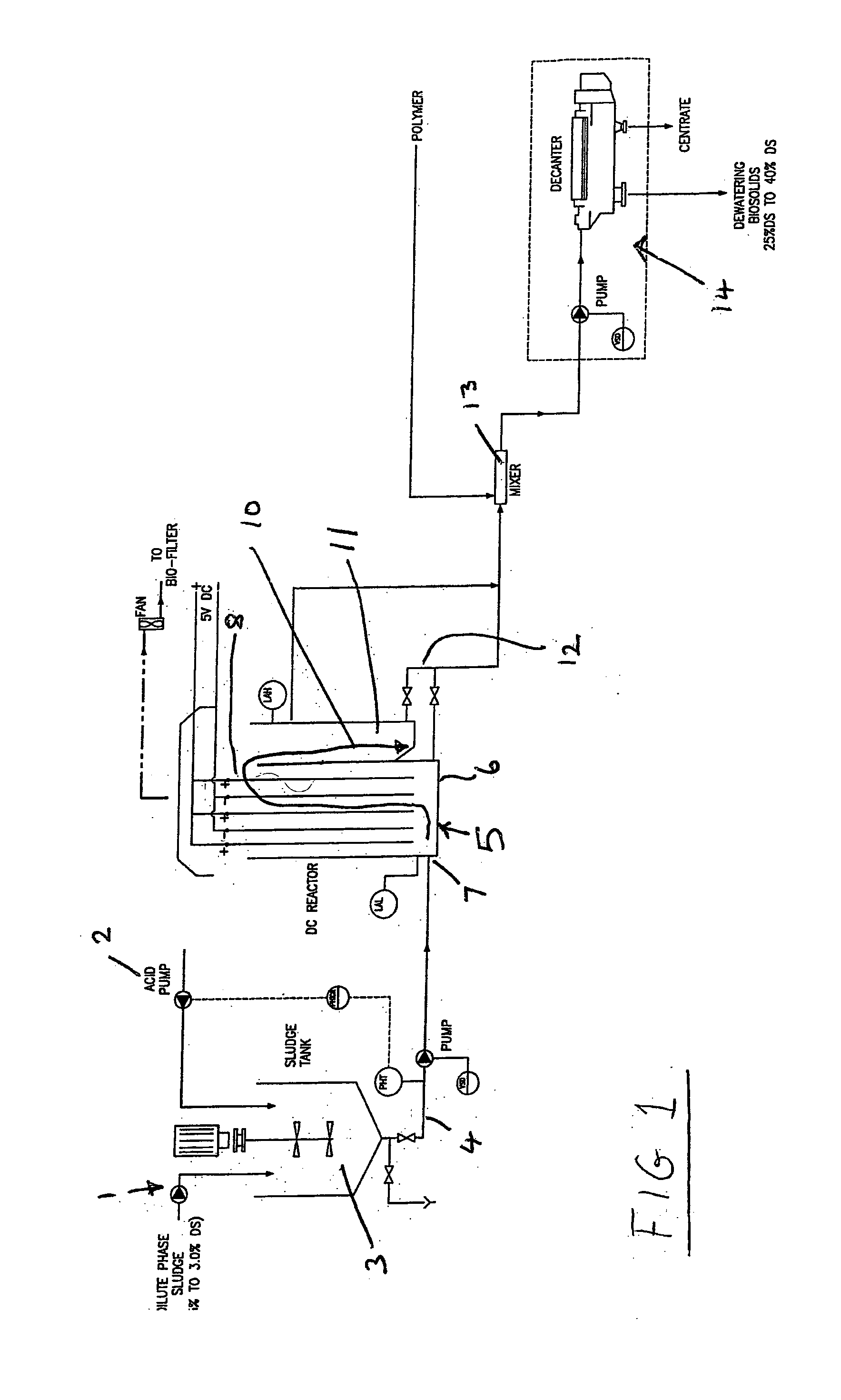
[0035]Referring to drawings dilute phase sludge typically 0.5 to 4% more particularly 2 to 3% dry solids is provided at 1 and mixed with acid provided from an acid pump 2. Typically the acid is sulphuric acid or hydrochloric acid. The sludge and acid is mixed in a mixer 3 and when thoroughly mixed is taken through outlet pipe 4 to reactor 5. A typical flow rate of the dilute phase sludge is from about 10 to about 100 m3 / h.

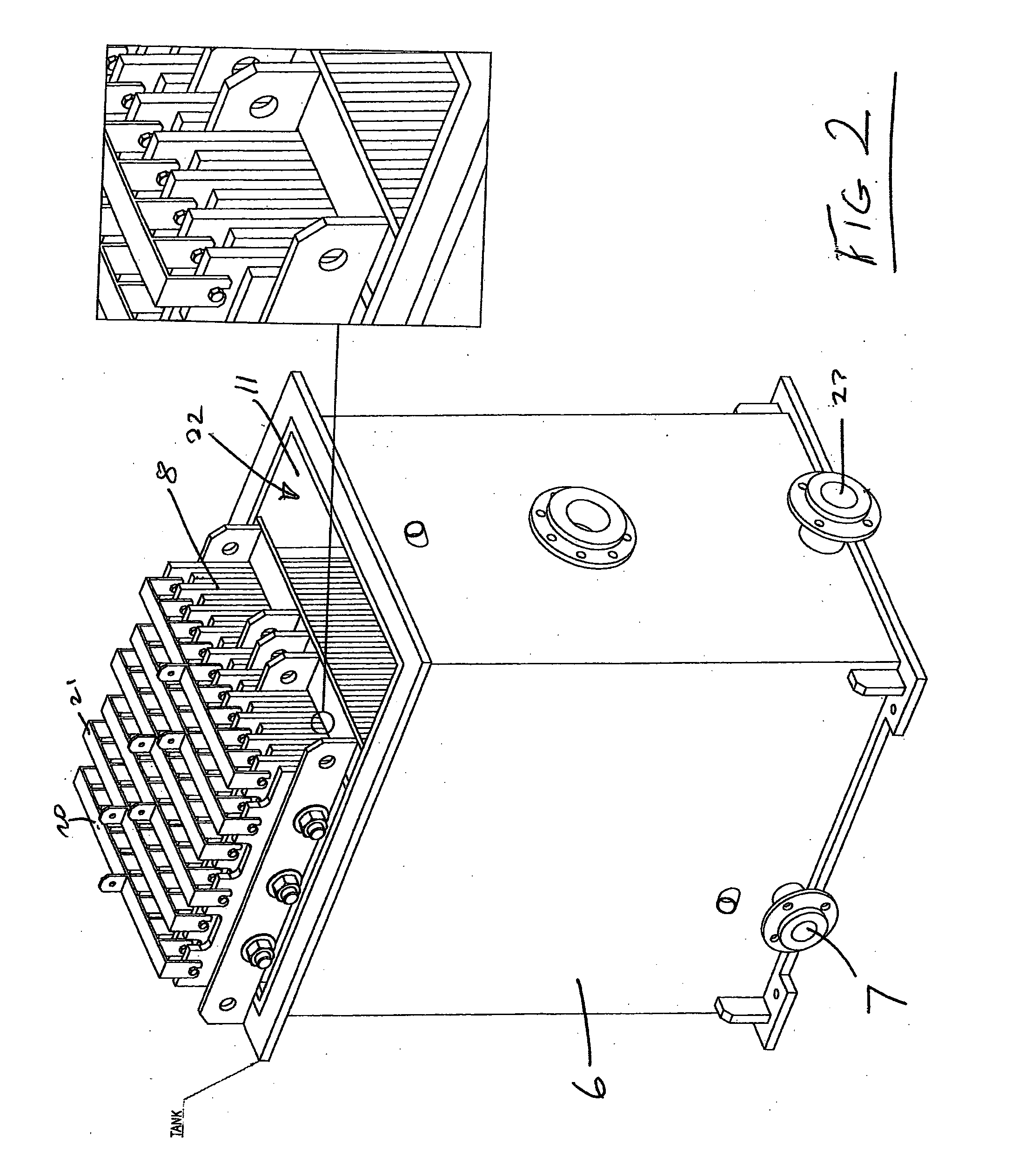
[0036]The reactor 5 applies a DC field across the sludge. The reactor 5 may comprise a holding vessel 6 with an inlet 7 towards to the bottom of the vessel 6. The vessel has therein a series of plates 8 across which the DC field is applied. In the example there are ten positive plates and ten negative plates. The gap between the plates is preferably from about 10 mm to about 30 mm. We have found about a gap of 15 mm gives good results.

[0037]Referring now to FIG. 2 the inlet 7 feeds to the interior of holding vessel 6 in which plates 8 are positioned. Positive and n...


PUM

PropertyMeasurementUnit
voltageaaaaaaaaaa
voltageaaaaaaaaaa
voltageaaaaaaaaaa

Abstract

The invention comprises a method of treating sludges which includes the steps of applying an electric field to the sludge to effect dewatering prior to further dewatering of the sludge. Typically the sludge comprises dilute phase sludge, and the electric field is a DC electric field. The pH of the sludge may be adjusted to between substantially 5 and substantially 6 prior to applying the electric field.

Description

TECHNICAL FIELD OF THE INVENTION[0001]This invention relates to a method of treating sludges and has been designed particularly though not necessarily solely for use in the treatment of biosolids.BACKGROUND ART[0002]The treatment of sewage sludge results in a final residue for disposal. This residue is often referred to as biosolids. The dry solids (DS) contents of the biosolids varies typically from 0.5% DS to 4% DS. The production of this dilute phase sludge from treated waste water depends on the type of treatment process used. Typically, the dilute phase is discharged from a process comprising of mesophilic digesters, thermophilic digesters, extended aeration, activated sludge, waste activated sludge, primary treatment, sequencing batch reactors and in certain processes combinations of the above.[0003]Typically the dilute phase is dewatered by applying pressure in belt presses, other type of presses, or decanter centrifuges. The dewatered cake typically has a concentration of 13...

Claims


Application Information

Patent Timeline
Patent Type & Authority Applications(United States)
IPC IPC(8): C02F11/12C02F9/12C02F11/14
CPCB01D21/0009C02F1/463C02F1/4696C02F1/4698C02F1/66C02F11/12B01D21/262C02F11/14C02F2001/46133C02F2201/4617C02F11/121B01D21/26C02F11/147C02F11/15Y02W10/37B01D21/01C02F9/00
Inventor FERNANDO, TISSA
Owner FDE PROCESS SYST
Why Eureka
Try Eureka