Dipper handle assembly for a power shovel

Active Publication Date: 2020-12-15
L&H IND
View PDF1 Cites 2 Cited by
  • Summary
  • Abstract
  • Description
  • Claims
  • Application Information

AI Technical Summary

Benefits of technology

[0008]It is one aspect of some embodiments of the present invention to provide a yoke comprised of a forged transition portion and forged lugs interconnected by a plurality of plates. One advantage of this configuration is that the grain structure of the forged components can be precisely controlled to provide increased tensile strength and fatigue resistance. Those of ordinary skill in the art will appreciate yoke transition portions are traditionally cast because they possess areas of varying thicknesses and of complex shapes, which m

Problems solved by technology

Those of ordinary skill in the art will appreciate yoke transition portions are traditionally cast because they possess areas of varying thicknesses and of complex sha

Method used


Image

  • Dipper handle assembly for a power shovel
  • Dipper handle assembly for a power shovel
  • Dipper handle assembly for a power shovel

Examples


Embodiment Construction

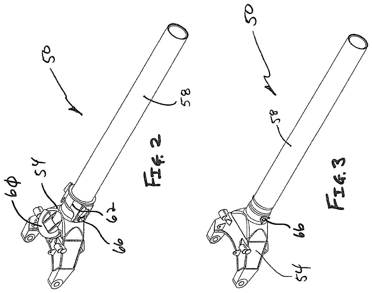
[0067]FIGS. 2-10 show a dipper handle assembly 50 of one embodiment of the present invention that is comprised of a yoke 54 interconnected to one and of a tube 58. FIG. 2 shows one embodiment of the present invention configured to use with rope crowd power shovels, wherein a D-ring 60 or sheave is provided that receives a rope. Here, a collar 62 may also be provided that interconnects the yoke 54 to the tube by way of a pin 66. FIG. 3 shows another configuration used with hydraulic crowd power shovels, wherein a hydraulic cylinder extends the length of the tube and connects to the yoke through an aperture by way of a pin, which will be described in further detail below.

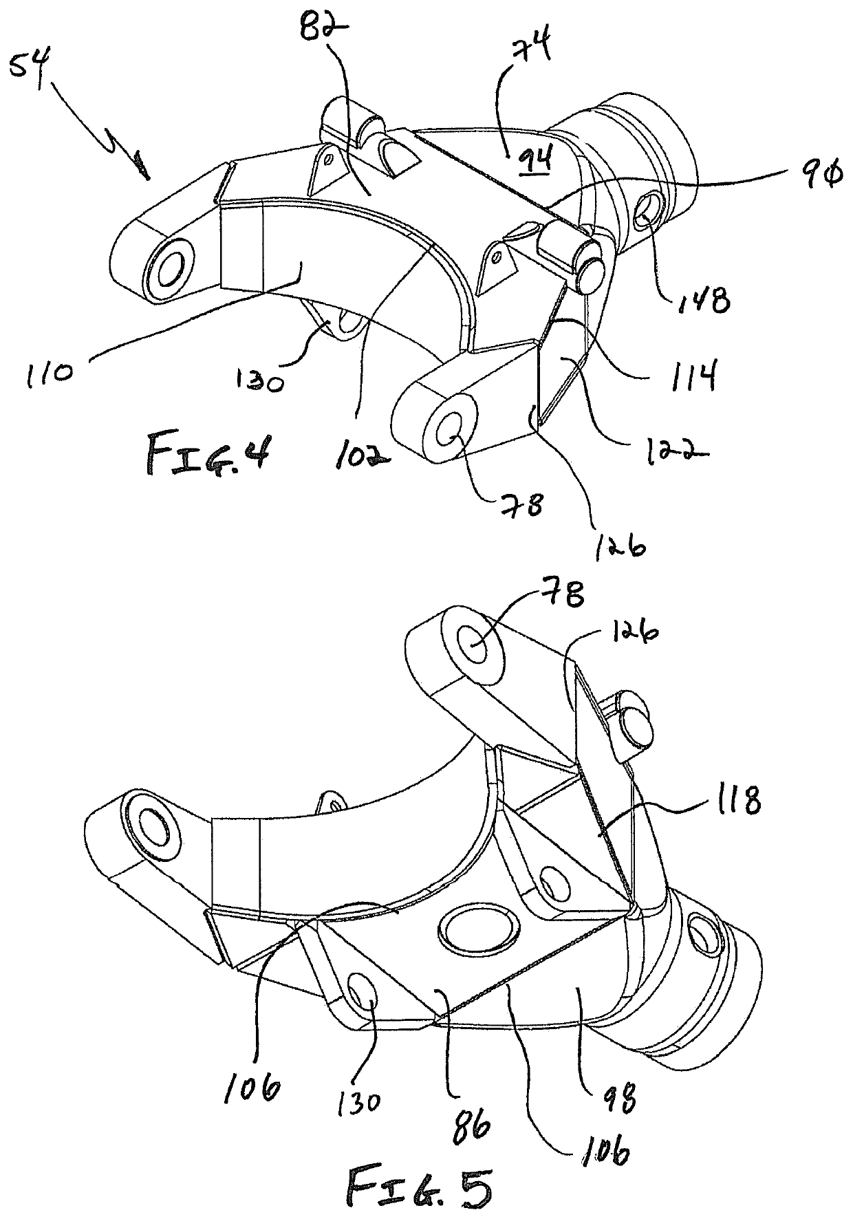
[0068]FIGS. 4-8 show the yoke 54 of one embodiment of the present invention. The yoke is comprised of a transition portion 74, which is interconnected to the tube 58 with a full-thickness weld 72. The transition portion 74 is interconnected to a series of interconnected plates that accommodate lugs 78. More specifical...


PUM


Abstract

A yoke for a dipper handle assembly used on a power shovel. The yoke is constructed at least in part of a transition portion and associated lugs manufactured of a forged material as opposed to castings. Accordingly, the yoke is less prone to failure and easy to repair in the field.

Description

[0001]This application claims the benefit of U.S. Provisional Patent Application No. 62 / 798,199, filed Jan. 29, 2019, the entirety of which being incorporated by reference herein.FIELD OF THE INVENTION[0002]Embodiments of the present invention are generally concerned with dipper handle assemblies used by power shovels. More specifically, an improved dipper handle yoke is disclosed.BACKGROUND OF THE INVENTION[0003]Power shovels, which are also known as stripping shovels, front shovels, electric mining shovels, or rope shovels, are common in the mining industry. FIG. 1 shows an example of a power shovel 1 manufactured by Caterpillar® as their Model 7495. The dipper 2, i.e. the shovel, is supported at an upper and by cables 6 operatively interconnect to a boom assembly 10. The boom assembly 10 is configured to selectively raise and lower the dipper 2, wherein the cables 6 control the dipper tilt angle. In operation, the dipper handle assembly 20 slides within the saddle block 24 to mov...

Claims


Application Information

Patent Timeline
IPC IPC(8): E02F3/36E02F3/42E02F3/02
CPCE02F3/3677E02F3/427E02F3/02E02F3/38
Inventor RHODINE, JORDAN T.HECHT, NATHANAEL S.
Owner L&H IND
Why Eureka
Try Eureka