Moving a free-standing structure between high and low adhesion states

a free-standing structure and adhesion state technology, applied in the field of free-standing structures, can solve the problems of devices undetected contact with the substrate, large adhesion forces in comparison,

Active Publication Date: 2010-09-23
QORVO US INC
View PDF16 Cites 41 Cited by
  • Summary
  • Abstract
  • Description
  • Claims
  • Application Information

AI Technical Summary

Benefits of technology

[0007]Embodiments disclosed herein generally solve a stiction problem in switching devices by moving the switch from a state of high adhesion to a landing electrode to a state of low adhesion to the landing electrode. Once in the low adhesion state, the switch can then be pulled away from contact with a lower force provided by either the spring constant of the switch and / or the electrostatic forces resulting from low voltages applied to nearby electrodes.
[0008]In one embodiment, a method of moving a switch in a micro-electromechanical device is disclosed. The method includes applying one or more pulses of first voltage to a first electrode to move the switch from a first position in contact with a second electrode where the switch is in a state of high adhesion with the second electrode to a second position different than the first position and in contact with the second electrode where the switch is in a state of low adhesion with the second electrode. The switch remains in contact with the second electrode during the movement from the first position to the second position. The one or more pulses of first voltage are each applied for a first period of time. The method may also include applying a second voltage to a third electrode to move the switch from the second position to a third position spaced from the second electrode. The second voltage may be applied for a second period of time that is greater than the first period of time.
[0009]In another embodiment, a method of moving a switch in a micro-electromechanical device is disclosed. The method includes applying a first voltage for a first period of time to a first electrode to move the switch from a first position spaced from a second electrode to a second position in contact with the second electrode, where the switch is in a state of low adhesion with the second electrode. The method also includes applying one or more pulses of a second voltage to the first electrode to move the switch from the second position to a third position in contact with the second electrode, where the switch is in a state of high adhesion with the second electrode. The switch remains in contact with the second electrode while moving from the second position to the third position. Each pulse may be applied for a second period of time less than the first period of time.
[0010]In another embodiment, a method of moving a switch in a micro-electromechanical device is disclosed. The method includes applying a first voltage for a first period of time to a first electrode to move the switch from a first position spaced from the first electrode to a second position in contact with the first electrode, wherein the switch is in a state of low adhesion with the first electrode. The method may also include applying one or more pulses of a second voltage to the first electrode to move the switch from the second position to a third position in contact with the first electrode, where the switch is in a state of high adhesion with the first electrode at the third position. The switch remains in contact with the first electrode while moving from the second position to the third position. Each pulse may be applied for a second period of time less than the first period of time.
[0011]In another embodiment, a method of operating a MEMS device is disclosed. The method includes applying a first voltage to a first electrode to move a switch from a first position spaced from landing area and a second position in contact with the landing area and measuring the resistance through the switch at the second position. The method may also include applying a second voltage to the first electrode to move the switch from the second position to a third position different than the second position and measuring the resistance through the switch at the third position.
[0012]In another embodiment, a method of operating a MEMS device is disclosed. The method includes applying a first voltage to a first pull-in electrode to bring a rocker plate into contact with a first landing electrode. The MEMS device includes the rocker plate coupled to a pivot contact, the first landing electrode spaced from the pivot contact, the first pull-in electrode disposed between the pivot contact and the first landing electrode, a second landing electrode spaced from the pivot contact and a second pull-in electrode disposed between the pivot contact and the second landing electrode. The method also includes measuring the first resistance through the rocker plate and applying one or more pulses of a second voltage to the first pull-in electrode. The method additionally includes measuring the second resistance through the rocker plate and applying one or more pulses of a third voltage to the first pull-in electrode. The method also includes measuring the third resistance through the rocker plate and applying a fourth voltage to the second pull-in electrode to move the rocker plate out of contact with the first landing electrode.

Problems solved by technology

One of the issues found in shrinking MEMS devices to the scale of less than a few micrometers is that the adhesion forces begin to be large in comparison to other restoring forces in the devices.
Once the adhesion forces become larger than the restoring forces, the device may undesirably remain in contact with the substrate.

Method used


Image

  • Moving a free-standing structure between high and low adhesion states
  • Moving a free-standing structure between high and low adhesion states
  • Moving a free-standing structure between high and low adhesion states

Examples


Embodiment Construction

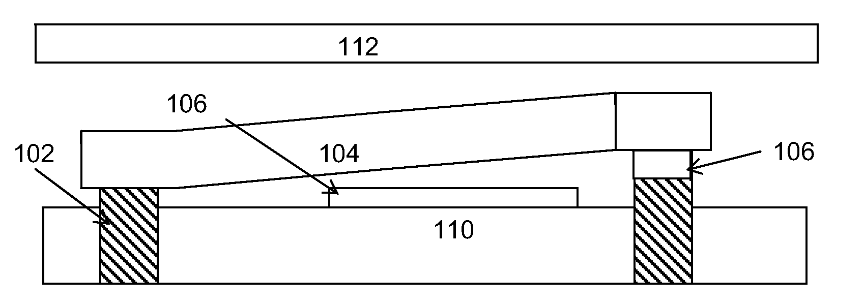
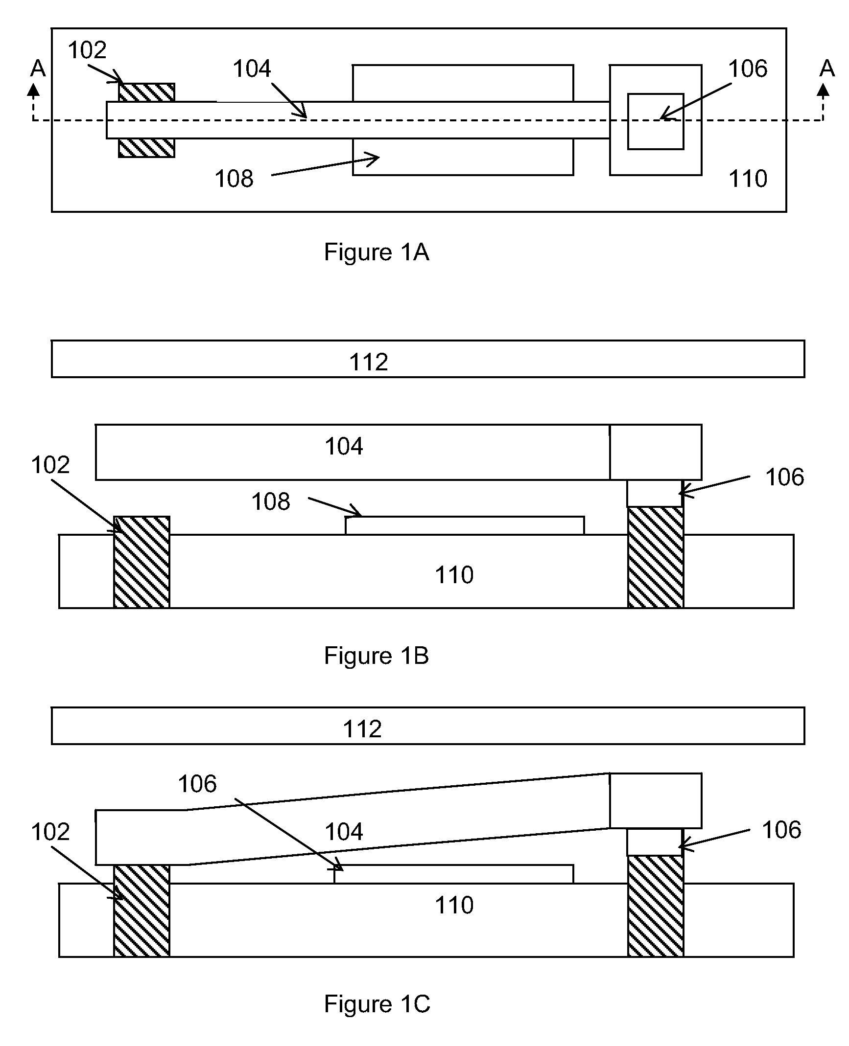
[0031]Embodiments disclosed herein generally solve a stiction problem in switching devices by using pulses of electrical voltage which take the switch from being strongly adhered to a landing electrode to the point where it is only weakly adhered. Once in the low adhesion state, the switch can then be pulled away from contact with a lower force provided by either the spring constant of the switch and / or the electrostatic forces resulting from low voltages applied to nearby electrodes. There is no need to pivot the switch off of the landing electrode with an additional, contacting and / or fulcrum electrode positioned between the landing electrode and the electrode connecting the switch to electrical contacts below the switch.

[0032]The embodiments will be illustrated by considering an electrostatically actuated cantilever device, which can act as a relay, which is either in contact with the landing electrode or spaced therefrom. When the device is in contact with the landing electrode,...


PUM


Abstract

Embodiments disclosed herein generally solve a stiction problem in switching devices by using a series of pulses of force which take the switch from being strongly adhered to a landing electrode to the point where it is only weakly adhered. Once in the low adhesion state, the switch can then be pulled away from contact with a lower force provided by either the spring constant of the switch and/or the electrostatic forces resulting from low voltages applied to nearby electrodes.

Description

BACKGROUND OF THE INVENTION[0001]1. Field of the Invention[0002]Embodiments of the present invention generally relate to a free standing structure such as a switch or cantilever and a method of moving the free standing structure between high and low adhesion states.[0003]2. Description of the Related Art[0004]As the size of semiconductor devices continues to shrink, so does the size of micro-electromechanical (MEMS) devices that are coupled to the semiconductors. MEMS devices may be used as miniature relay switches, capacitance switches, non-volatile memory elements and for many more applications. The MEMS devices have a switch or cantilever that moves between at least two positions to either permit or deny a current from flowing through the switch. In other MEMS devices the cantilever moves between being in contact with a landing electrode to not being in contact. In some of these devices no current flows, but a change in the capacitance of the landing region occurs.[0005]MEMS devi...

Claims


Application Information

Patent Timeline
Patent Type & Authority Applications(United States)
IPC IPC(8): H02N1/00
CPCG11C23/00H01H1/0036H01H59/0009H01H2059/0063H01H2059/0036H01H2059/0054H01H2001/0047
Inventor SMITH, CHARLES GORDONKNIPE, RICHARD L.
Owner QORVO US INC
Why Eureka
Try Eureka