Multi-cavity LED array RGB collimation optic

a collimation optic and led array technology, applied in the field of optical devices, can solve the problems of traditional optics lacking color uniformity enhancement features, difficult for light engines to collimate to a narrow beam, and historically difficult to achieve color uniformity, so as to enhance the color uniformity of collimated light beams

Active Publication Date: 2010-09-23
LIGHTING SCI GROUP +1
View PDF8 Cites 42 Cited by
  • Summary
  • Abstract
  • Description
  • Claims
  • Application Information

AI Technical Summary

Benefits of technology

[0013]The combined effect of these uniformity and collimation features is to collimate a relatively wide-angle light beam emitted by an LED array into a relatively narrow-angle collimated light beam, such that color uniformity of the collimated light beam is enhanced.

Problems solved by technology

By themselves, light engines are historically difficult to both collimate to a narrow beam as well as achieve acceptable color uniformity.
Traditional optics lack sufficient color uniformity enhancement features, and project regions of light with high discrete, non-homogenized intensities of the individual primary colors red, green and blue.
Poor composite color uniformity is produced as a result, which is not desirable for some applications.

Method used


Image

  • Multi-cavity LED array RGB collimation optic
  • Multi-cavity LED array RGB collimation optic
  • Multi-cavity LED array RGB collimation optic

Examples


Embodiment Construction

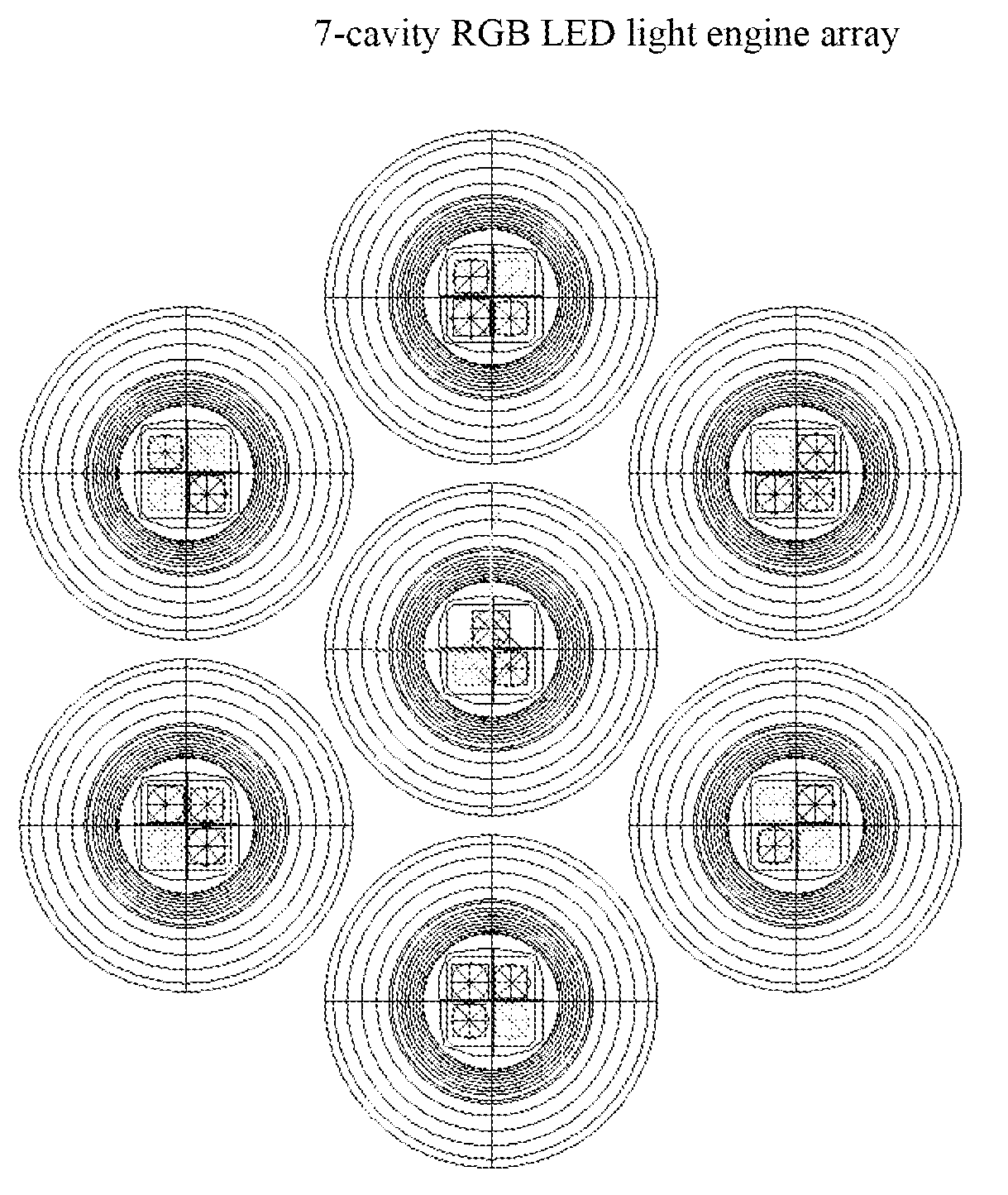
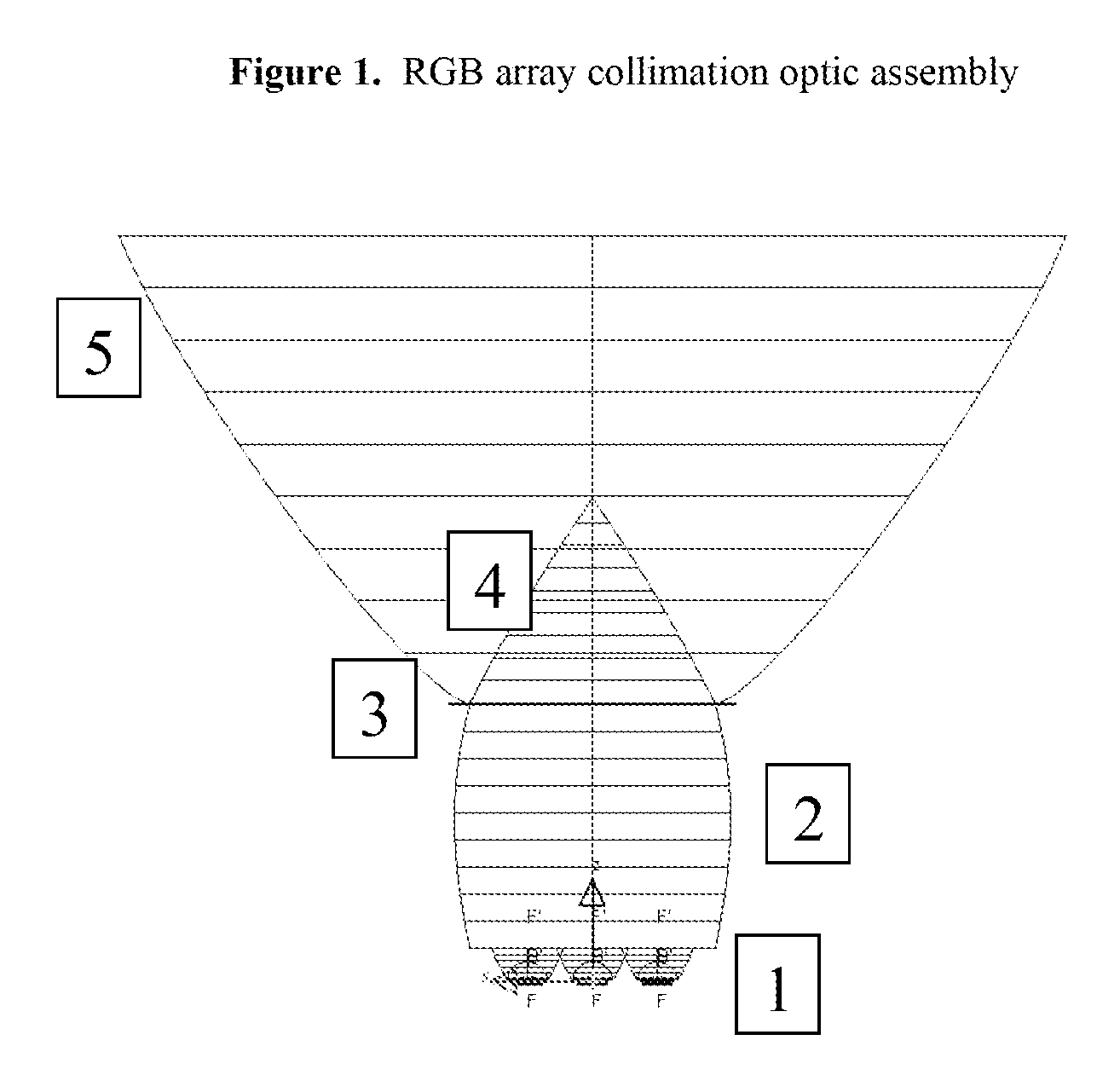
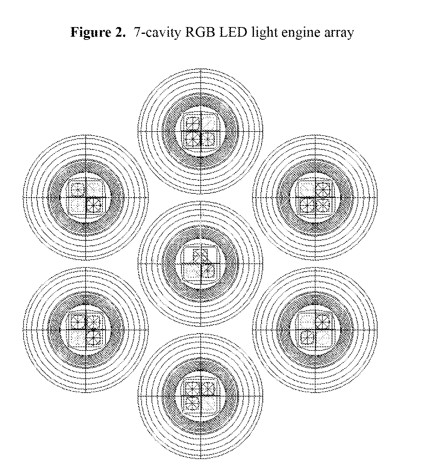
[0023]Features of an embodiment of the present invention are shown in FIG. 1. The reflecting cavity 2, lenslet array 3, cone lens 4 and reflector 5 are collectively referred to herein as the collimation optic. The collimation optic is used to decrease the intensity dispersion of a multi-cavity wide beam, e.g., 60 degree primary light engine cavity 1 in which the light emitters include light emitting diodes of different primary wavelengths, and wherein 60 degree refers to the beam angle of the light collectively emitted by the light engine cavities 1. The multi-cavity 60 degree primary light engine may for example be the 7-cavity Lamina Titan™ light engine. A light engine with other than 7 cavities may also be used, so long as the beam angle of the emitted light, prior to any collimation optics, is approximately 60 degrees and the field angle is approximately 100 degrees.

[0024]Light exiting the LED array 1 disperses at approximately a 60 degree beam angle. The light then proceeds to ...


PUM


Abstract

This invention relates to optical devices. More specifically, the present invention relates to a collimated optical light source assembly that produces a uniform white light. Specifically, light from a multi-cavity RGB LED array is dispersed in a reflecting cavity having a Lambertian texture on the interior surface. The light is then emitted though a lenslet array and a cone lens which together further disperses the light emitted by the individual LEDs. The dispersed light is then collimated by a reflector.

Description

[0001]This application claims the benefit of U.S. provisional application No. 60 / 976,693, filed on Oct. 1, 2007, the entire disclosure of which is incorporated by reference.[0002]References including various publications may be cited and discussed in the description of this invention. Any citation and / or discussion of such references is provided merely to clarify the description of the present invention and is not an admission that any such reference is “prior art” to the present invention. All references cited and discussed in this specification are incorporated herein by reference in their entirety and to the same extent as if each reference was individually incorporated by reference.FIELD OF THE INVENTION[0003]This invention relates to optical devices. More specifically, the present invention relates to collimated optical light source assemblies that produce a uniform white light.BACKGROUND OF THE INVENTION[0004]Entertainment, architectural and theater industries have application...

Claims


Application Information

Patent Timeline
Patent Type & Authority Applications(United States)
IPC IPC(8): F21V9/16F21V7/00F21V1/00G02B27/30
CPCF21K9/00G02B19/0028G02B19/0066F21K9/68
Inventor BAILEY, EDWARD
Owner LIGHTING SCI GROUP
Why Eureka
Try Eureka