Optical network unit

Active Publication Date: 2010-09-23
NIPPON TELEGRAPH & TELEPHONE CORP
View PDF6 Cites 20 Cited by
  • Summary
  • Abstract
  • Description
  • Claims
  • Application Information

AI Technical Summary

Benefits of technology

[0043]According to the present invention, there can be implemented ONU that is enabled without changing the MAC function after the type of a received downstream signal is confirmed as being for P-P. That is, this ONU is set to a disable state when it is misconnected to PON, and thus there can be avoided a problem that another user using the same optical splitter cannot communic

Problems solved by technology

Particularly in the optical access network using PON architecture, a problem oc

Method used


Image

  • Optical network unit
  • Optical network unit
  • Optical network unit

Examples


Example

Embodiment 1

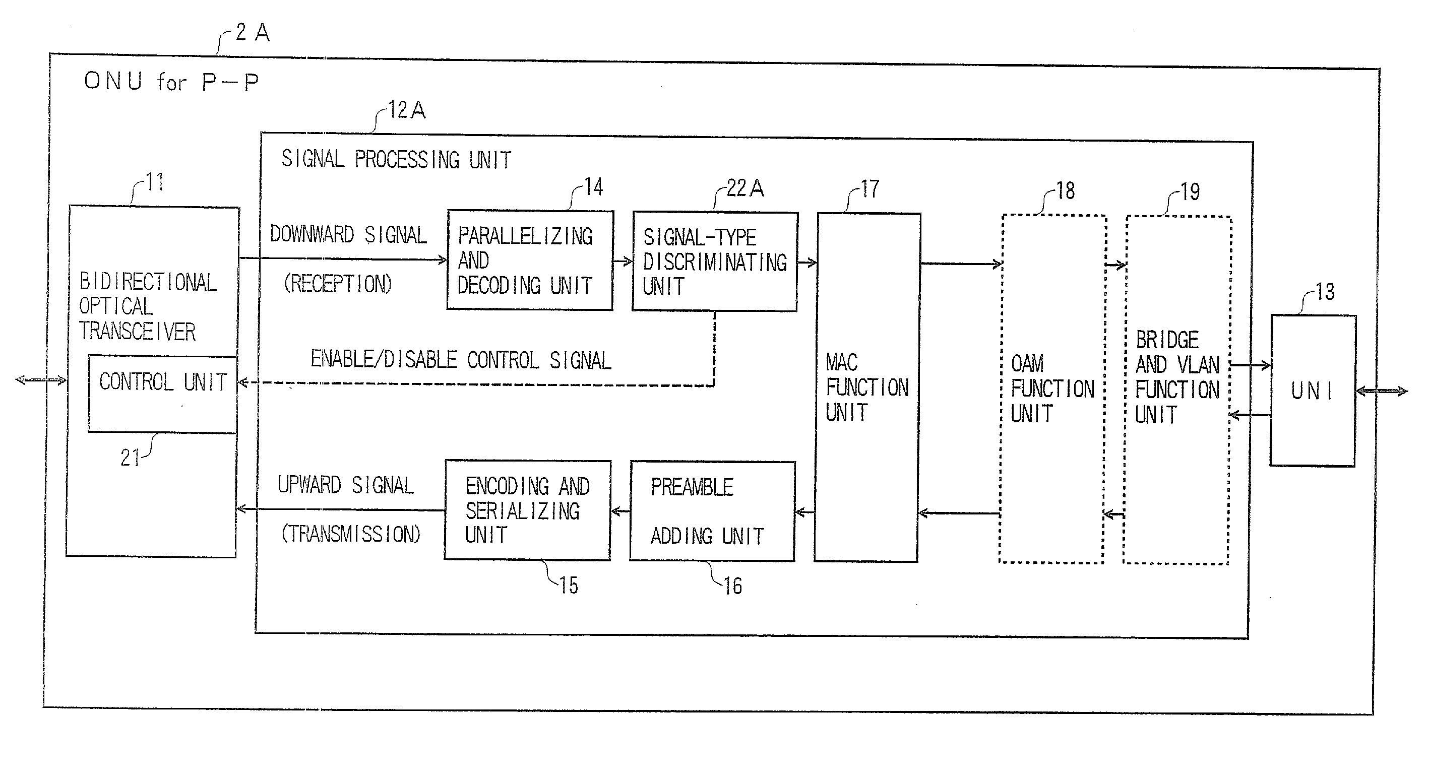
[0056]FIG. 4 shows an example of the construction of ONU for P-P of an embodiment 1 according to the present invention. ONU for P-P of the embodiment 1 is configured so that an optical transmitter Tx is controlled from a disable state (Disable) to an enable state (Enable) after a downstream signal corresponding to an optical access network construction is discriminated to be for P-P.

[0057]In FIG. 4, ONU 2A for P-P has a bidirectional optical transceiver 11, UNI 13 and a signal processing unit 12A. The signal processing unit 12A for communicating with OLT 101 for P-P shown in FIG. 1A in one-to-one correspondence has a parallelizing and decoding unit 14, an encoding and serializing unit 15, a preamble adding unit 16, an MAC function unit 17 and a signal-type discriminating unit 22A, and it has an OAM function unit 18 and a bridge and VLAN function unit 19 as required.

[0058]The bidirectional optical transceiver 11 has a function of bidirectionally communicating with OLT 101...

Example

Embodiment 2

[0081]FIG. 5 shows an example of the construction of an adaptive ONU according to an embodiment 2 of the present invention. The adaptive ONU of the embodiment 2 determines whether the downstream signal is for P-P or for PON, executes the signal processing for P-P or for PON according to the type of the downstream signals, and controls the enable state of the optical transmitter Tx. The same constituent elements as those in the embodiment 1 are represented by the same reference numerals.

[0082]In FIG. 5, the adaptive ONU 2B has a bidirectional optical transceiver 11, UNI 13 and a signal processing unit 12B. The signal processing unit 12B which controls communication with OLT for P-P in one-to-one correspondence or with OLT for PON in one-to-multiple correspondence has a parallelizing and decoding unit 14, an encoding and serializing unit 15, a preamble adding unit 16, an MAC function unit 17, and OAM function unit 18, a bridge and VLAN function unit 19, an MPMC function un...

Example

Embodiment 3

[0101]FIG. 6 shows the construction of ONU of an embodiment 3 according to the present invention. Adaptive ONU of the embodiment 3 operates as ONU for P-P or ONU for PON in accordance with the type of the downstream signal by a construction different from that of the embodiment 2.

[0102]In FIG. 6, the adaptive ONU is configured so that in the place of the MPMC function validation / invalidation switching unit 23 of the embodiment 2, first switch units 27-1, 27-2 and 28-1, 28-2 are arranged before and after the MPMC function unit 20, and any one of the MPMC function unit 20 and the bypass path is selected as a path of the downstream signal and the upstream signal. Furthermore, it is configured so that in place of the preamble adding unit 16 and the preamble format switching unit 24 of the embodiment 2, the preamble adding unit 25 for PON and the preamble adding unit 26 for P-P are arranged in parallel, the second switch units 29-1, 29-1 are arranged before and after the prea...


PUM


Abstract

ONU 2A for P-P includes a signal-type discriminating unit 22A that discriminates whether a type of a downstream signal transmitted from OLT is for the P-P or not, and outputs an enable/disable control signal that controls an optical transmitter to an enable state or a disable state, and a control unit 21 that controls the optical transmitter to the enable state or the disable state according to the enable/disable control signal, wherein the signal-type discriminating unit 22A outputs to the control unit 21 a disable control signal that controls the optical transmitter to the disable state under an initial state before the type of the downstream signal is discriminated, and outputs to the control unit 21 an enable control signal that controls the optical transmitter to the enable state after the downstream signal is discriminated to be for the P-P.

Description

CROSS-REFERENCE TO RELATED APPLICATION[0001]This application is a U.S. National Stage application claiming the benefit of prior filed International Application Number PCT / JP2008 / 066826, filed on Sep. 18, 2008, in which the International Application claims priority from Japanese Patent Application Number 2007-285110, filed on Nov. 1, 2007, the entire contents of which are incorporated herein by reference.TECHNICAL FIELD[0002]The present invention relates to an optical network unit disposed on a user side of an optical access network.BACKGROUND ART[0003]FIGS. 1A and 1B show examples of the construction of an optical access network.[0004]FIG. 1A shows an example of the construction of an optical access network of a point-to-point access (one-to-one correspondence) type. The point-to-point access will be hereinafter referred to as “P-P”. In the optical access network using P-P architecture, an optical line terminal (OLT) 101 for P-P and an optical network unit (ONU) 102 are connected to...

Claims


Application Information

Patent Timeline
IPC IPC(8): H04B10/24H04L12/44
CPCH04J14/0282H04Q11/0067H04Q2011/0079
Inventor KANI, JUNICHIFUJIMOTO, YUKIHIROKUBO, RYOGOOKADA, MITSUMASA
Owner NIPPON TELEGRAPH & TELEPHONE CORP
Why Eureka
Try Eureka