Cleaning appliance

a technology for cleaning appliances and cleaning equipment, applied in the direction of cleaning filter means, cleaning equipment, suction filters, etc., can solve the problems of dragging uncontrollable over the surface, spherical body to rotate, or fall, and main body to be unable to return to the upright position

Inactive Publication Date: 2010-09-30
DYSON TECH LTD
View PDF45 Cites 86 Cited by
  • Summary
  • Abstract
  • Description
  • Claims
  • Application Information

AI Technical Summary

Benefits of technology

[0022]The appliance preferably comprises a chassis connected to the rolling assembly, preferably to the main body of the rolling assembly, and each support member is preferably connected to this chassis. The chassis preferably comprises a body connected to the rolling assembly and a pair of side portions connected to, or integral with, the body of the chassis. Each side portion preferably has a front wall, with the walls being mutually inclined at an angle in the range from 60 to 120°. Each of the support members is preferably movable relative to the chassis, and is preferably located behind one of the side portions of the chassis so that the chassis can shield the support members from impact with walls, furniture or other items upstanding from the floor surface.
[0023]Each of the support members is preferably pivotably connected to a respective side portion of the chassis so that the orientation of the support members relative to the chassis may be changed, thereby changing the direction in which the cleaning appliance moves over the floor surface. The appliance preferably comprises a plurality of moveable steering arms each connecting a respective one of the support members to the chassis. Each of these steering arms is preferably pivotably connected to the chassis, and more preferably at or towards the end of a respective side portion of the chassis. Each of the steering arms is preferably substantially L-shaped so as to extend about its respective support member to shield it from impact with any items located on the floor surface.

Problems solved by technology

The shape of the vacuum cleaner means that there is a tendency for the spherical body to rotate, or fall, on to one of the wheels over as it is pulled over a floor surface using the hose and wand assembly, and subsequently to be dragged uncontrollably over the surface.
While the main body is arranged so that the centre of gravity of the main body is located in a position in which the main body will tend to return itself to an upright position, there is a risk that the main body may not be able to return to the upright position, for example if it is located against a wall or other item located on the floor surface

Method used


Image

  • Cleaning appliance
  • Cleaning appliance
  • Cleaning appliance

Examples


Embodiment Construction

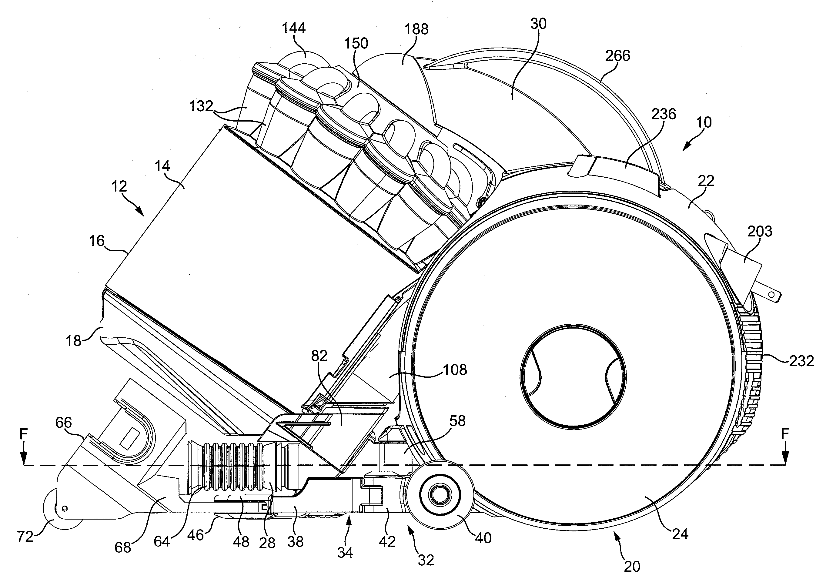
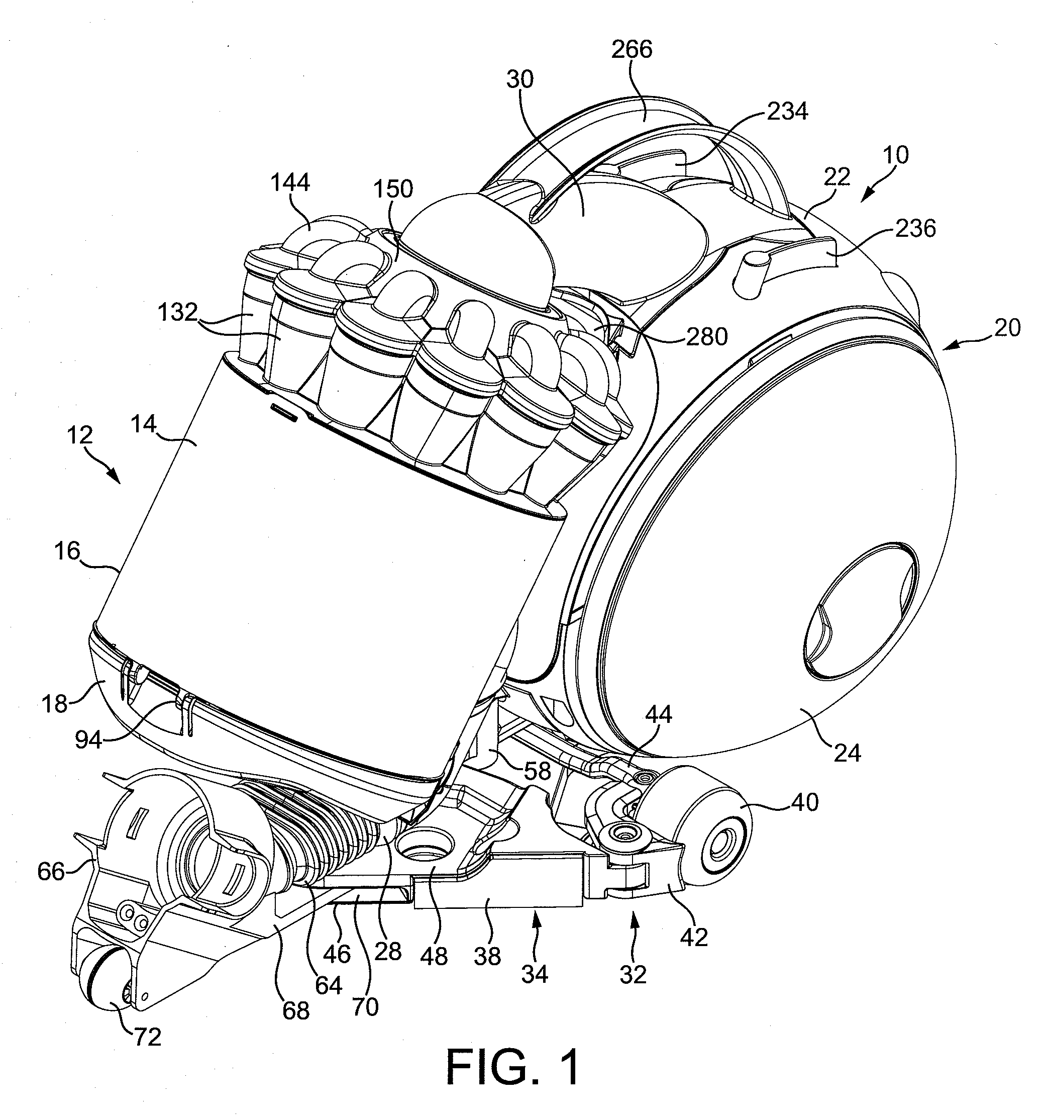
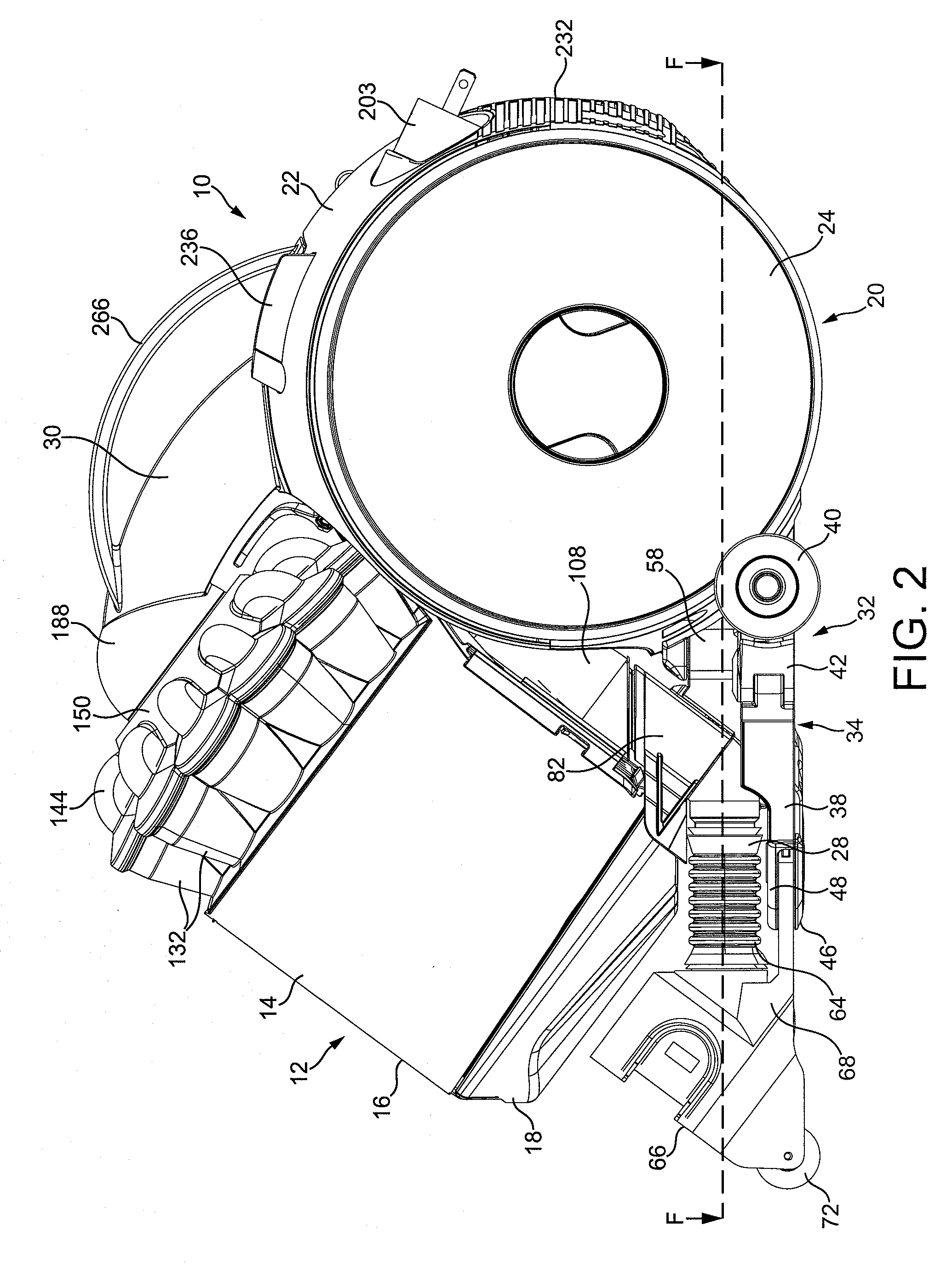
[0058]FIGS. 1 to 4 illustrate external views of a cleaning appliance in the form of a vacuum cleaner 10. The vacuum cleaner 10 is of the cylinder, or canister, type. In overview, the vacuum cleaner 10 comprises separating apparatus 12 for separating dirt and dust from an airflow. The separating apparatus 12 is preferably in the form of cyclonic separating apparatus, and comprises an outer bin 14 having an outer wall 16 which is substantially cylindrical in shape. The lower end of the outer bin 14 is closed by curved base 18 which is pivotably attached to the outer wall 16. A motor-driven fan unit for generating suction for drawing dirt laden air into the separating apparatus 12 is housed within a rolling assembly 20 located behind the separating apparatus 12. The rolling assembly 20 comprises a main body 22 and two wheels 24, 26 rotatably connected to the main body 22 for engaging a floor surface. An inlet duct 28 located beneath the separating apparatus 12 conveys dirt-bearing air ...


PUM


Abstract

A cleaning appliance of the canister type includes a substantially spherical floor engaging rolling assembly including a fluid inlet for receiving a fluid flow and a device for acting on the fluid flow received through the inlet, and a plurality of floor engaging support members for supporting the rolling assembly as it is manoeuvred over a floor surface.

Description

REFERENCE TO RELATED APPLICATIONS[0001]This application claims the priority of United Kingdom Application No. 0905482.6, filed Mar. 31, 2009, the entire contents of which are incorporated herein by reference.FIELD OF THE INVENTION[0002]The present invention relates to a cleaning appliance.BACKGROUND OF THE INVENTION[0003]Cleaning appliances such as vacuum cleaners are well known. The majority of vacuum cleaners are either of the “upright” type or of the “cylinder” type (called canister or barrel machines in some countries). Cylinder vacuum cleaners generally comprise a main body which contains a motor-driven fan unit for drawing a dirt-bearing fluid flow into the vacuum cleaner, and separating apparatus, such as a cyclonic separator or a bag, for separating dirt and dust from the fluid flow. The dirt-bearing fluid flow is introduced to the main body through a suction hose and wand assembly which is connected to the main body. The main body of the vacuum cleaner is dragged along by t...

Claims


Application Information

Patent Timeline
Patent Type & Authority Applications(United States)
IPC IPC(8): A47L9/00
CPCA47L5/362A47L9/00A47L9/009A47L9/327A47L9/1641A47L9/242A47L9/1625A47L11/40
Inventor DYSON, JAMESGAMMACK, PETER DAVIDHEATLEY-ADAMS, EMMA JANECOULTON, ROBERT MARK BRETT
Owner DYSON TECH LTD
Why Eureka
Try Eureka