Method for initializing indicating instrument for vehicle

a technology for indicating instruments and vehicles, applied in the direction of instruments, calibration apparatus, dynamo-electric converter control, etc., can solve the problem of reducing the accuracy of the initialization of the electrical angle corresponding to the stopper position, the control of the drive signal contains errors, and the unintended synchronization loss of the step motor

Inactive Publication Date: 2010-09-30
DENSO CORP
View PDF7 Cites 7 Cited by
  • Summary
  • Abstract
  • Description
  • Claims
  • Application Information

AI Technical Summary

Benefits of technology

[0011]According to the present invention, there is provided a method for initializing an indicating instrument for a vehicle. The instrument includes a pointer, a step motor, a rotary drive system, a stopper mechanism, and a control means. The pointer is rotatable in a zero-reset direction to return to a zero position, which indicates a zero value of a vehicle state value of the vehicle. The step motor includes a field winding and is configured to rotate the pointer upon application of a drive signal, which alternates in accordance with an electrical angle, to the field winding. The rotary drive system ranges from the step motor to the pointer. The stopper mechanism is configured to stop the pointer, which rotates in the zero-reset direction, at a stopper position located within a predetermined range from the zero position in the zero-reset direction. The control means is for controlling the drive signal based on a zero point, which is the electrical angle that corresponds to the stopper position. According to the method, zero-reset process...

Problems solved by technology

In consequence, if the initialization of the electrical angle that corresponds to the stopper position is inaccurate, the drive signal control contains an error from the beginning, i.e., before product shipment.
Because of this, there is concern in the worst case that unintended synchronization loss of the step motor is ...

Method used


Image

  • Method for initializing indicating instrument for vehicle
  • Method for initializing indicating instrument for vehicle
  • Method for initializing indicating instrument for vehicle

Examples


first embodiment

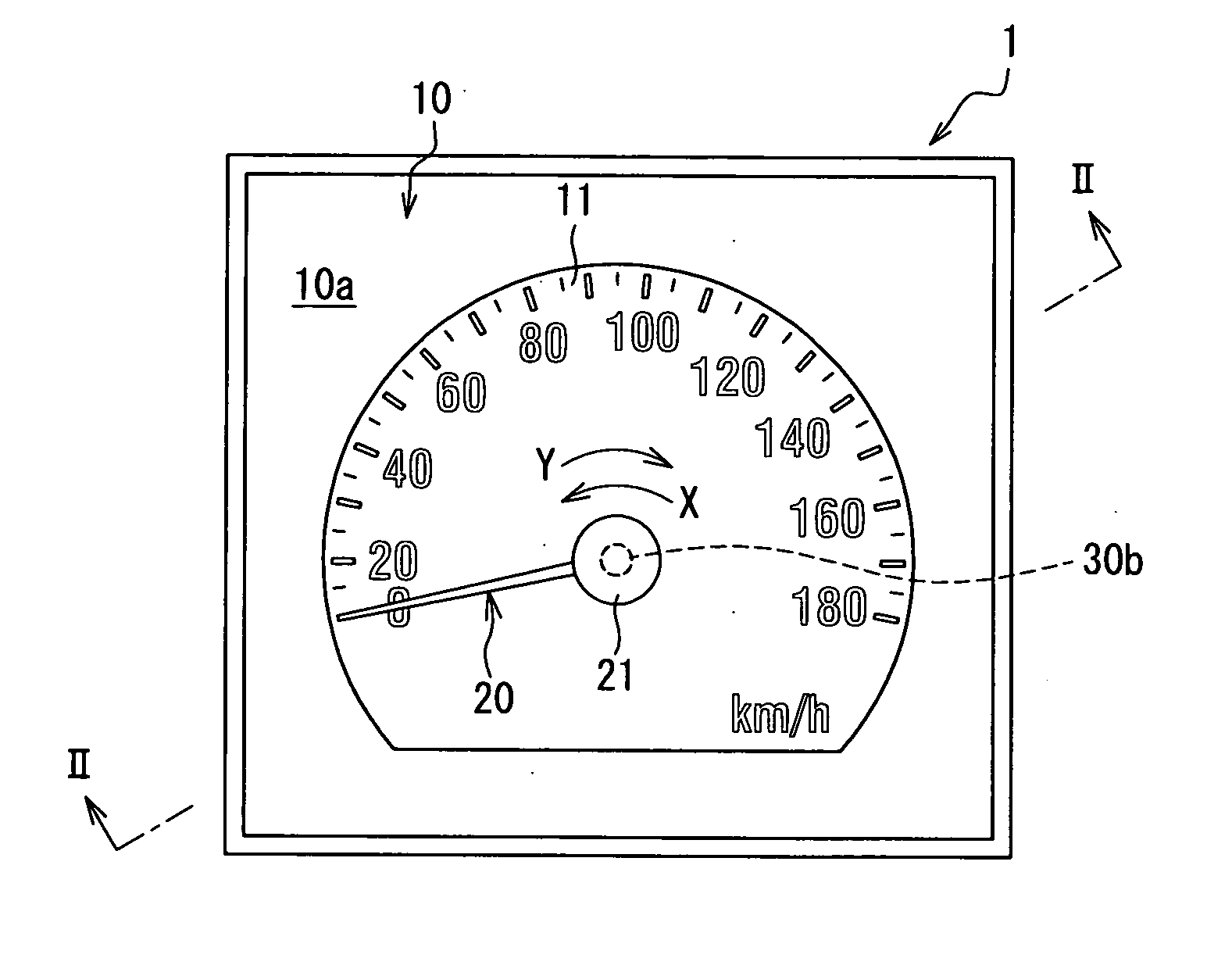
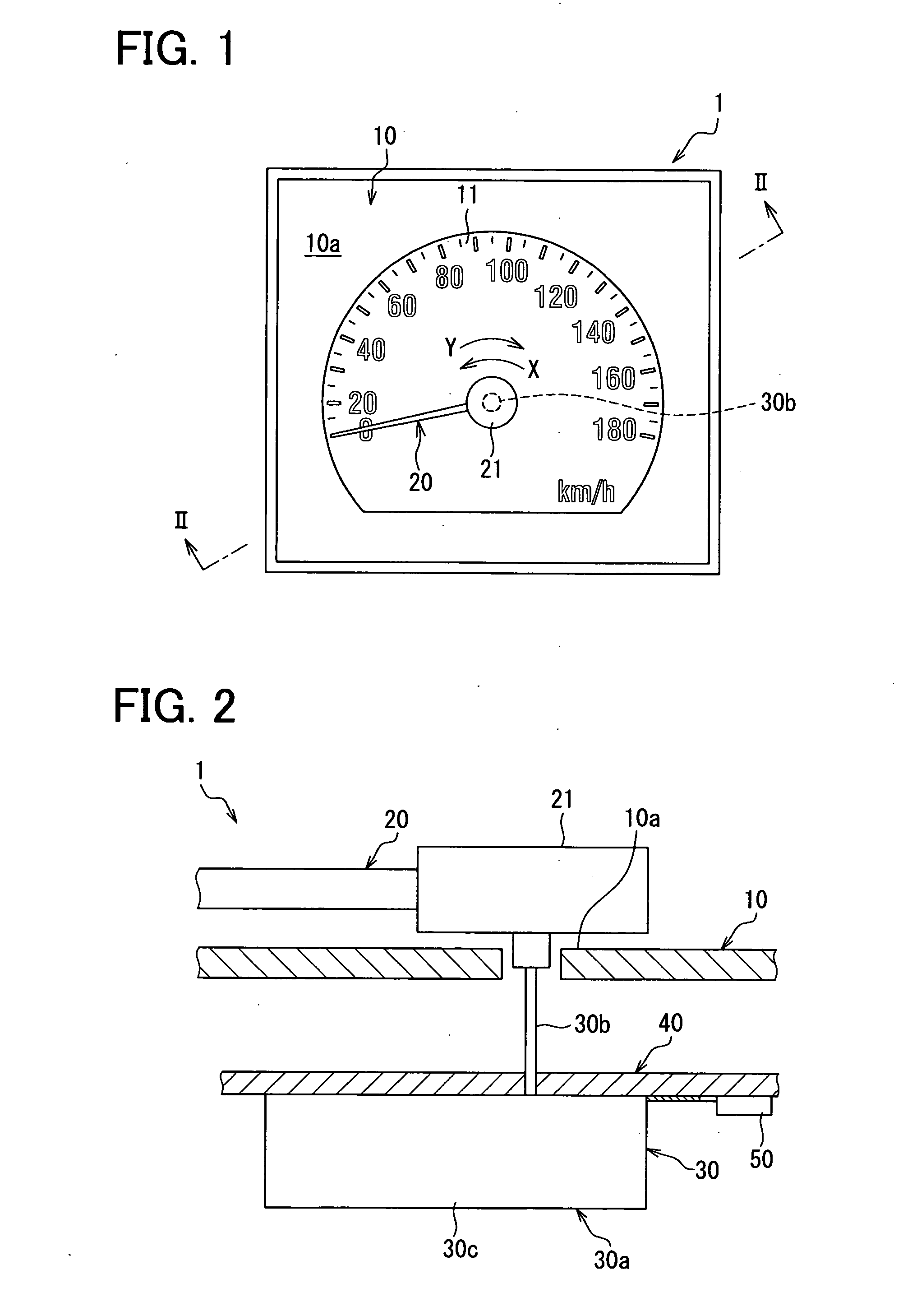
[0033]A first embodiment of the invention will be described below with reference to the accompanying drawings. FIG. 1 illustrates an indicating instrument 1 for a vehicle according to the first embodiment, to which a method for initialization of the invention is applied. The indicating instrument 1 is disposed in front of a driver seat inside the vehicle as a vehicle speed meter. As illustrated in FIGS. 1 to 3, the indicating instrument 1 includes an instrument board 10, a pointer 20, a rotating inner device 30, a board 40, and a control unit 50. The control unit 50 may serve as a control means.

[0034]The instrument board 10 illustrated in FIGS. 1 and 2 is disposed with its display surface 10a directed toward the driver seat, and includes a vehicle speed display 11 that displays a vehicle speed value as a vehicle state value. The vehicle speed display 11 displays vehicle speed values in a shape of a circular arc from a zero value (0 km / h), which is a reference for the vehicle speed v...

second embodiment

[0061]A second embodiment of the invention is a modification of the first embodiment. In initialization operation of the second embodiment, as illustrated in FIG. 11, a procedure S200 is performed prior to execution of procedures S101 to S104. More specifically, at S200, a frequency counter N set in a memory 52 is incremented. The frequency counter N is set at a zero value (0 times) immediately after a start of the initialization operation.

[0062]After the execution of S104, in the initialization operation of the second embodiment, procedures S205 to S208 instead of S105 in the first embodiment are executed. More specifically, at S205, it is determined whether the frequency counter N of the memory 52 has reached a predetermined number Ns. Two times is used as the predetermined number Ns in the present embodiment. If negative determination is made as a result of such a procedure S205, control returns to S200 to perform the following procedures S101 to S104 again. On the other hand, if...

third embodiment

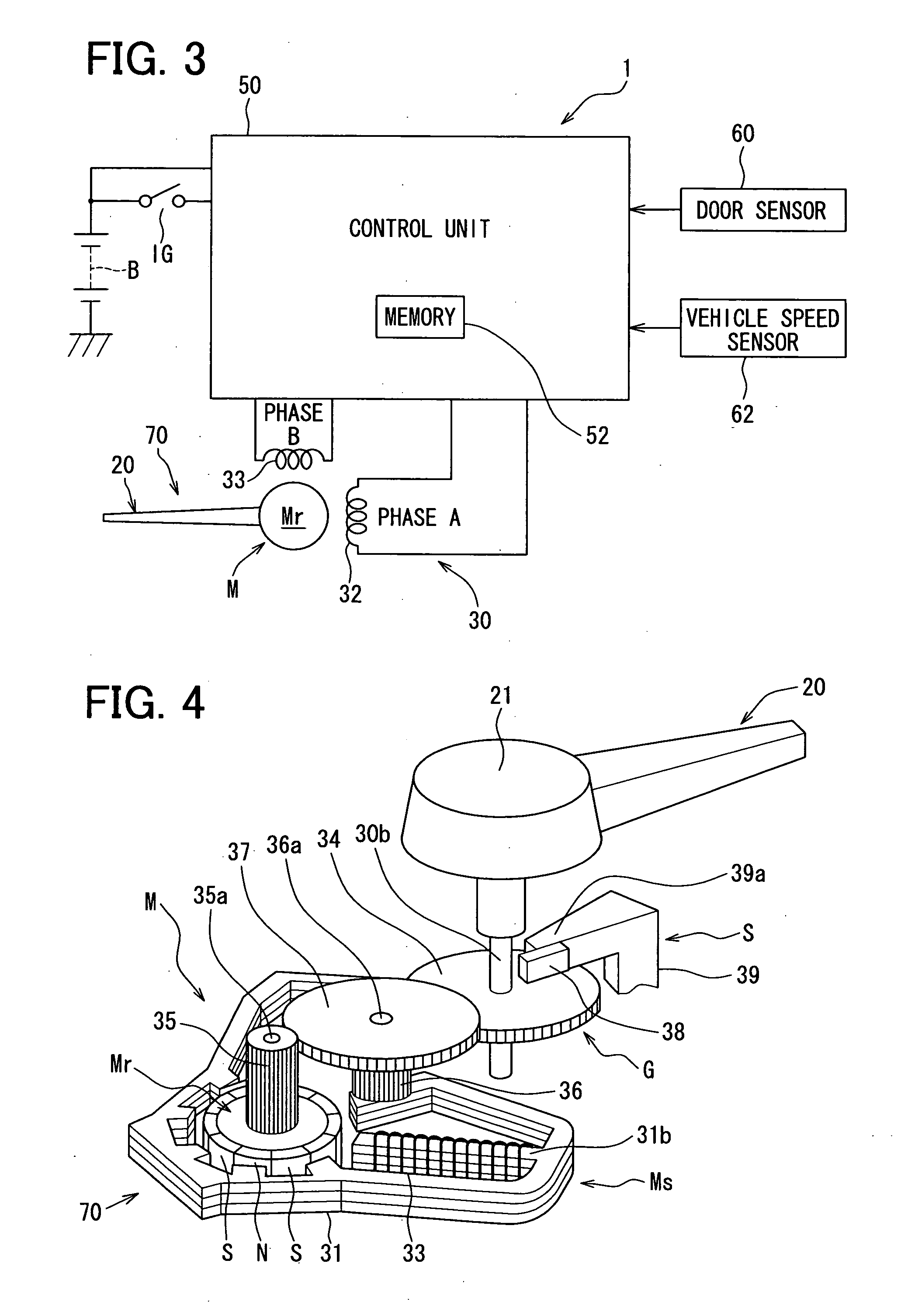
[0066]A third embodiment of the invention is a modification of the first embodiment. In initialization operation of the third embodiment, as illustrated in FIG. 12, procedures S301 to S303 are performed prior to execution of a procedure S101. More specifically, at S301, by controlling the electrical angle of the A-phase and B-phase drive signals applied to the field windings 32, 33, the electrical angle at the execution start of this procedure S301 is changed by a minute angle δθ in the zero-reset direction X. By setting the angle δθ at the control angle δθ described in the first embodiment, the pointer 20 is rotated to a position corresponding to this angle δθ in the zero-reset direction X.

[0067]At S302, it is determined, whether a complete stop of the pointer 20 by way of the rotational position change of the pointer 20 photographed by the camera 102 has been produced, based on the detection signal outputted from an image processing circuit 104. The complete stop is the following ...


PUM


Abstract

According to a method for initializing an indicating instrument for a vehicle, zero-reset processing is performed. In the zero-reset processing, a control device is made to control a drive signal to rotate a pointer in a zero-reset direction in order to force a step motor to lose synchronization. Furthermore, synchronization loss detection processing is performed. In the detection processing, a physical phenomenon generated in a rotary drive system due to forcible synchronization loss of the motor during the zero-reset processing, is detected. Then, an electrical angle of the drive signal at a time of detection of the phenomenon is selected as a synchronization loss electrical angle. Finally, zero point setting processing is performed. In the setting processing, the electrical angle phase-shifted from the synchronization loss electrical angle in an indication value increasing direction by 180 degrees or less, is set as a zero point stored in the control device.

Description

CROSS REFERENCE TO RELATED APPLICATION[0001]This application is based on and incorporates herein by reference Japanese Patent Application No. 2009-75028 filed on Mar. 25, 2009.BACKGROUND OF THE INVENTION[0002]1. Field of the Invention[0003]The present invention relates to a method for initializing an indicating instrument for a vehicle.[0004]2. Description of Related Art[0005]Conventionally, an indicating instrument for a vehicle is known. The indicating instrument rotates a pointer through application of a drive signal, which alternates in accordance with an electrical angle, to a field winding of a step motor, and indicates a vehicle state value which accords with a rotational position of the pointer. In such an indicating instrument, the pointer returns to a zero position, which indicates a zero value of the vehicle state value, as a result of rotation of the pointer in a zero-reset direction, and the pointer is stopped at a stopper position, which is located within a predetermin...

Claims


Application Information

Patent Timeline
IPC IPC(8): G12B13/00
CPCG01R7/06G01D2213/10
Inventor NAKANE, HIDEYUKI
Owner DENSO CORP
Why Eureka
Try Eureka