Power line data acquisition

Active Publication Date: 2010-09-30
AREVA NP INC
View PDF20 Cites 4 Cited by
  • Summary
  • Abstract
  • Description
  • Claims
  • Application Information

AI Technical Summary

Problems solved by technology

Such diagnostic equipment can only be used during the plant outages, which can be as long as 18 months apart in nuclear plants.
The work performed during the diagnostic is labor intensive and requires two to three technicians and, depending on the environment, the test operators can be subjected to undesirable levels of radiation, temperature or chemical hazards.
However, this solution requires external cabling routed around the plant floor, and a limited number of signals brought together per centry.

Method used


Image

  • Power line data acquisition
  • Power line data acquisition
  • Power line data acquisition

Examples


Embodiment Construction

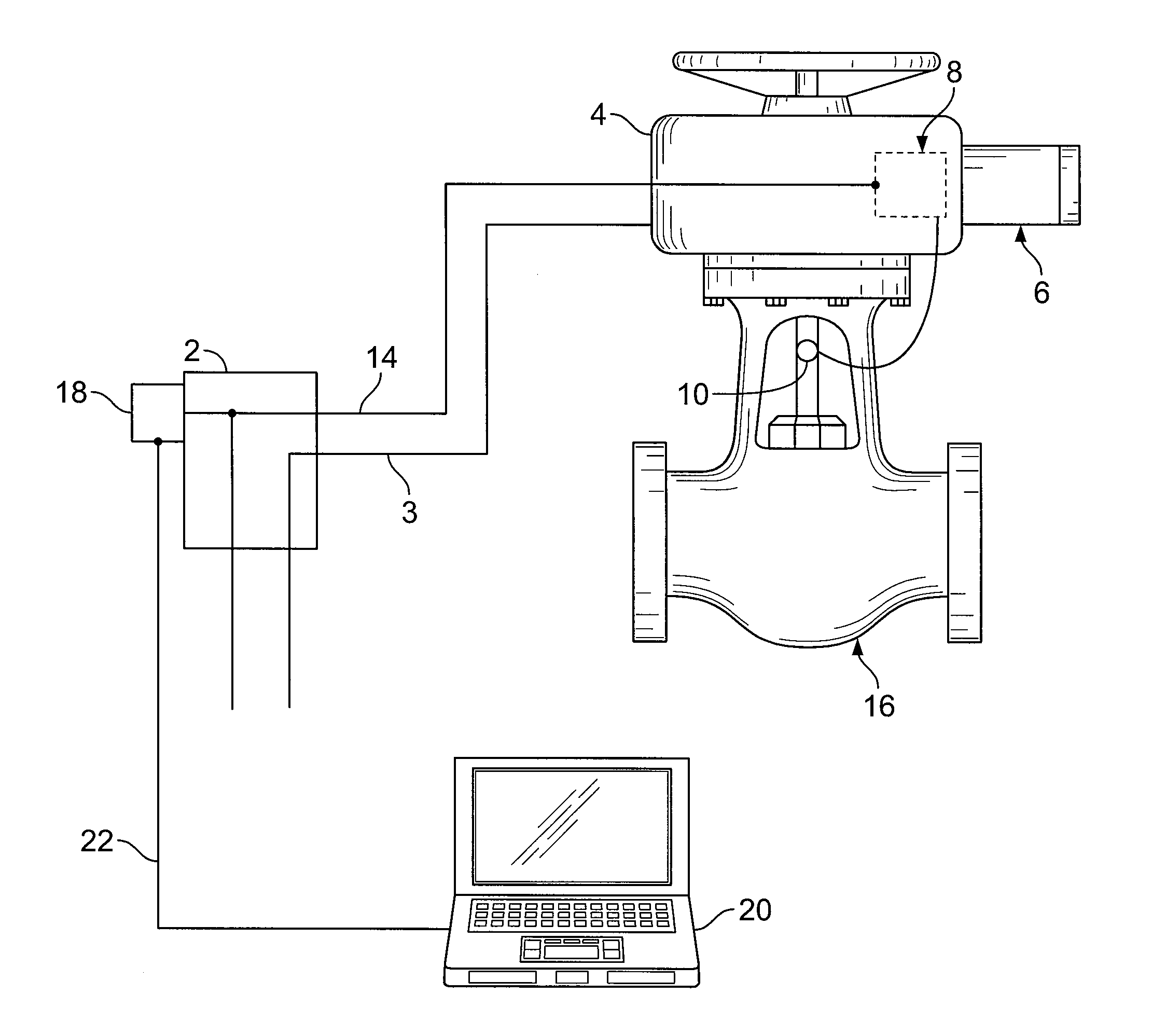
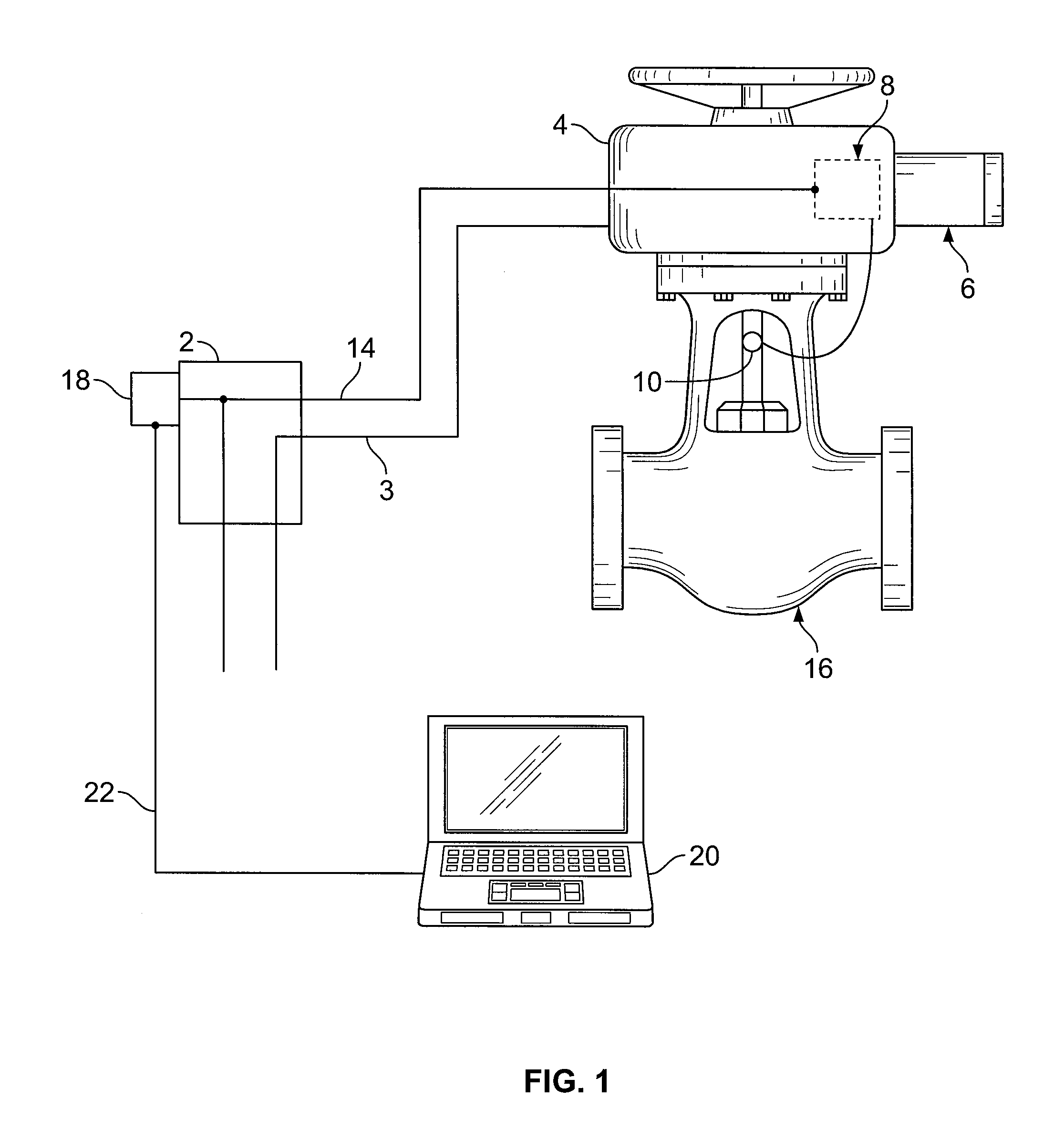
[0014]A diagnostic system in accordance with an embodiment of the present invention includes of a transmitter located at the MOV location and a receiver located at the MOV cable termination point such as the MCC. Data is transmitted via permanently installed electronics in the MOV switch box housing. The existing wiring (data transmission and power) connects the MOV to the outside of the safety boundary. Outside the safety boundary, the signals can be networked using computer controlled switch boxes that can drastically increase the number of valves that can be monitored. The signals can also be networked for diagnostics of multiple valves. The existing MOV cables may be ‘energized lines’ such as a torque switch, limit switches, light indicator lights and heater lines, or ‘non-energized lines’ such as spare lines that were installed but not being used. The present invention requires no additional digital acquisition electronics inside the plant floor.

[0015]FIG. 1 shows a MOV assembl...


PUM


Abstract

A motor operated valve diagnostic data acquisition system including: a motor operated valve assembly; a transmitter, the transmitter being permanently connected in a housing of a motor operated valve assembly; a receiver, the transmitter transmitting signals to the receiver via motor operated valve cables, the cables being existing motor operated valve cables; and electronic circuitry connected to the receiver, the electronic circuitry processing the signals received by the receiver.

Description

[0001]Priority to U.S. Provisional Patent Application Ser. No. 61 / 211,165 filed Mar. 26, 2009, is claimed, the entire disclosure of which is hereby incorporated by reference.[0002]The present invention relates generally to nuclear power plants, and more particularly to the motor operated valves.BACKGROUND[0003]Currently, safety related motor operated valves (MOV) are tested at the valve location using portable diagnostic equipment. Such diagnostic equipment can only be used during the plant outages, which can be as long as 18 months apart in nuclear plants. The work performed during the diagnostic is labor intensive and requires two to three technicians and, depending on the environment, the test operators can be subjected to undesirable levels of radiation, temperature or chemical hazards.[0004]One proposed solution to this problem is to install additional wiring to and from the MOV through the containment penetrations to the motor control center (MCC) outside the containment. The ...

Claims


Application Information

Patent Timeline
IPC IPC(8): F16K51/00
CPCH02K11/0078F16K37/0083G01L5/12G01L5/00G01L5/0042F16K37/0041H02K11/35Y10T137/0318Y10T137/8175Y10T137/8158
Inventor ATAMAN, VEDAT T.MCKEAGUE, LEW
Owner AREVA NP INC
Why Eureka
Try Eureka