Dimming interface for power line

a technology of power line and interface, applied in the field of electronic lighting, can solve the problems of inefficient use of space, limited aggregate output, and inability to produce discrete levels of light outpu

Inactive Publication Date: 2010-09-30
GENERAL ELECTRIC CO
View PDF13 Cites 25 Cited by
  • Summary
  • Abstract
  • Description
  • Claims
  • Application Information

AI Technical Summary

Benefits of technology

[0007]According to another aspect, a control circuit for a dimming interface circuit for controlling an electric device comprises a MOSFET that has a source coupled to a first resistor and a drain coupled to a sec...

Problems solved by technology

This approach has the drawback of only being able to produce discrete levels of light output.
With each ballast only able to produce a single light output, the aggregate output is limited to what the various combinations of the ballasts present can produce.
Moreover, this setup also requires multiple lamps for the same space to be lighted, resulting in an inefficient use of space.
One drawback in such a system is that as the voltage of the high frequency signal is diminished,...

Method used


Image

  • Dimming interface for power line
  • Dimming interface for power line
  • Dimming interface for power line

Examples


Embodiment Construction

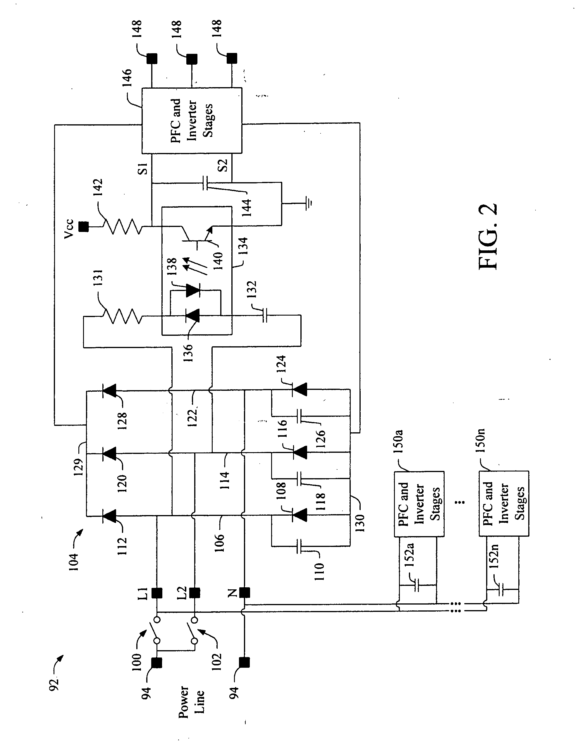
[0012]The following relates to a dimming interface or ballast for a power line. The dimming ballast mitigates capacitive loading caused by non-dimming interfaces or ballasts coupled to the same power line. The described dimming ballast is insensitive to the capacitive loading caused by non-dimming ballasts.

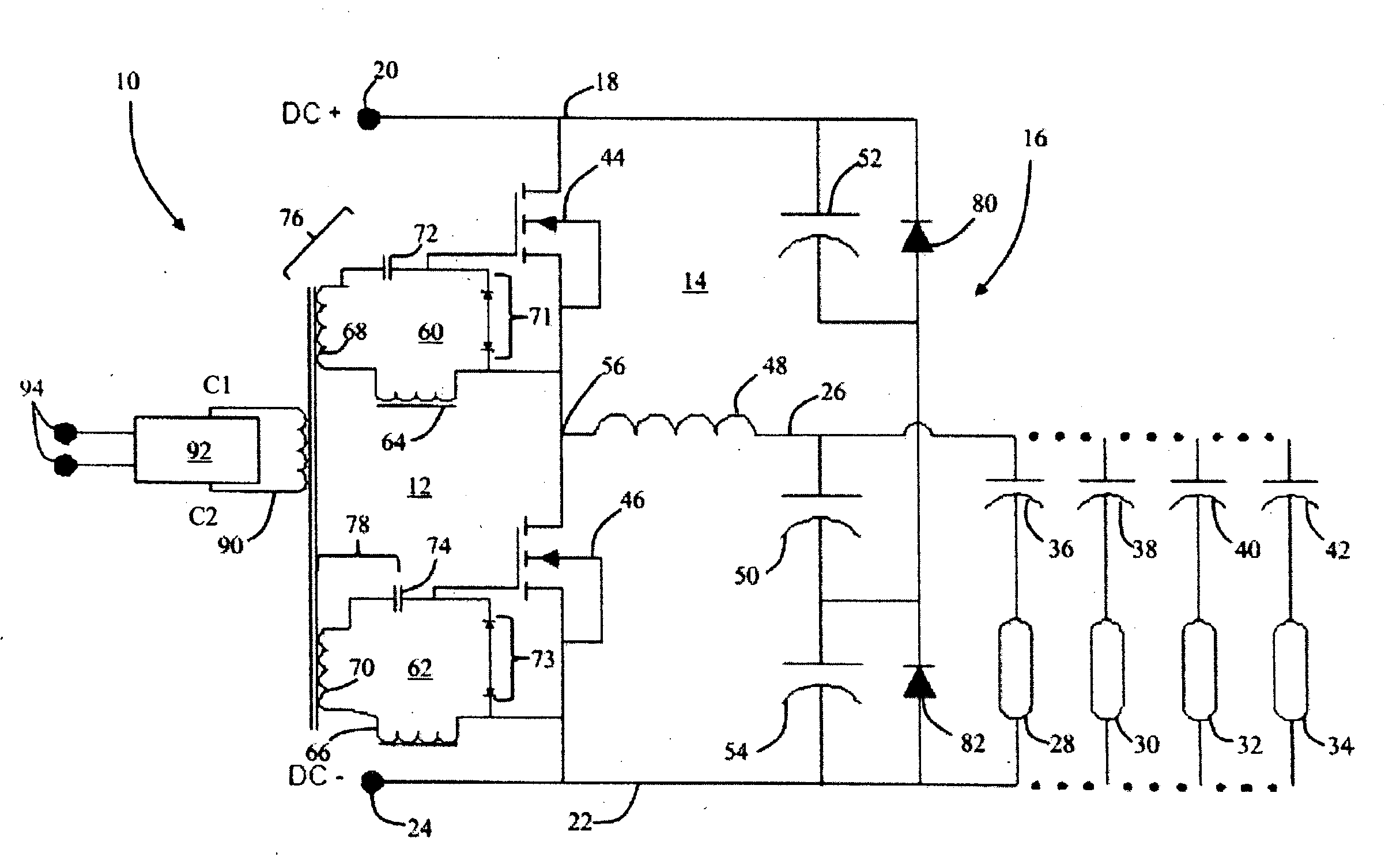
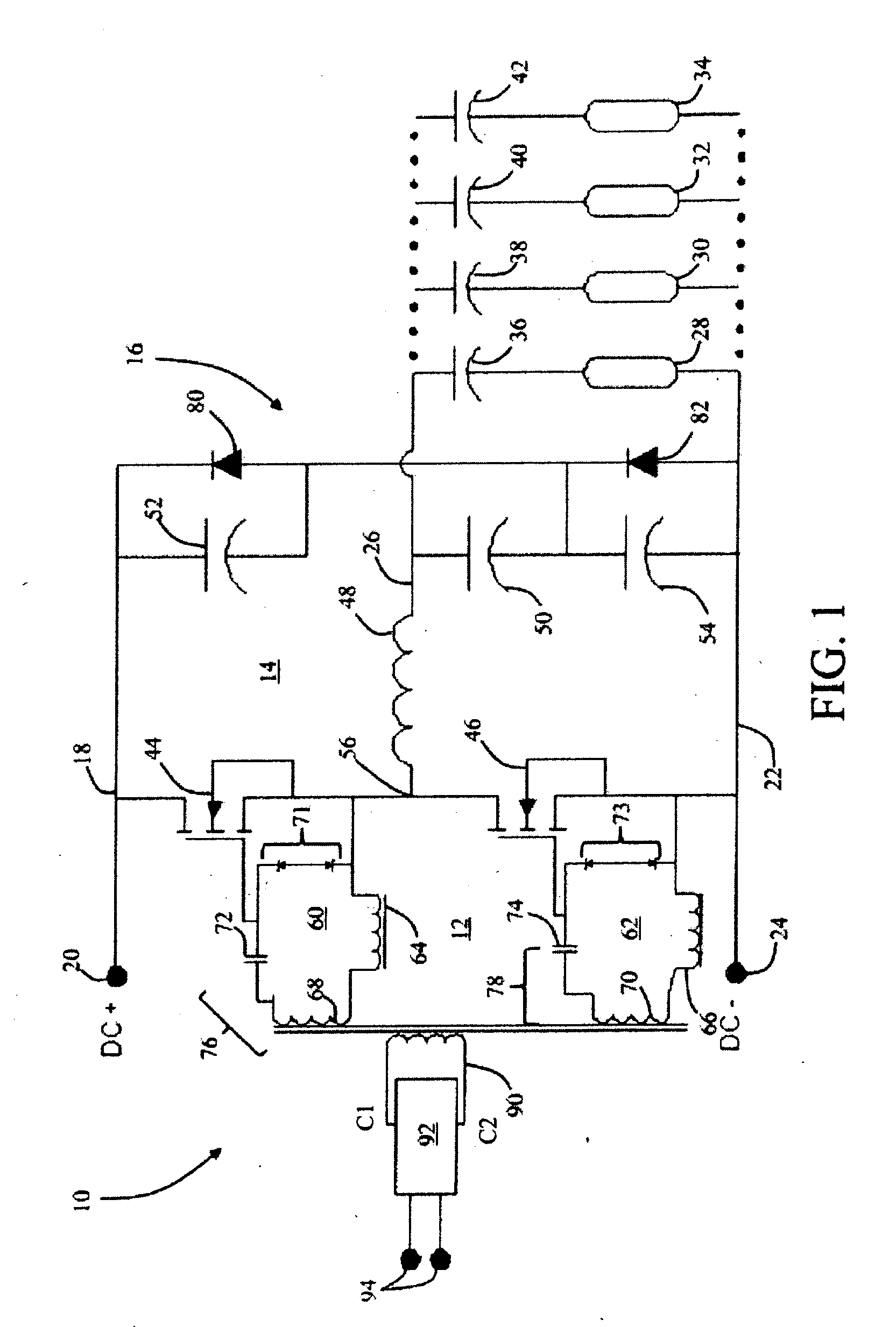
[0013]With reference to FIG. 1, a ballast circuit 10, such as an instant start ballast or the like, which may be employed in conjunction with the herein-described dimming interface circuit 92. The ballast circuit includes an inverter circuit 12 resonant circuit or network 14, and a clamping circuit 16. A DC voltage is supplied to the inverter 12 via a positive bus rail 18 running from a positive voltage terminal 20. DC voltage is derived from the PFC stage. The circuit 10 completes at a common conductor 22 connected to a ground or common terminal 24. A high frequency bus 26 is generated by the resonant circuit 14 as described in more detail below. First, second, third, through nth...


PUM


Abstract

An interface circuit for a lamp ballast includes first and second input power lines, L1 and L2, with first and second respective switches, and a neutral power line N, all coupled to a diode bridge. Closing one of the first or second input power lines L1 or L2 causes a photodiode in an opto-isolator coupled to the diode bridge to turn ON, which in turn causes a MOSFET in a control circuit to be in an open state. When in the open state, a first resistor coupled to the source of the MOSFET is included in the control circuit and causes a lamp attached thereto to operate in a dimmed state. When both input power line switches are closed, L1 and L2 are both coupled to the diode bridge and thereby cause the phototransistor to be in an OFF state, which causes the MOSFET to close, thereby including a second resistor, coupled to the drain of the MOSFET, in the control circuit in parallel with the first resistor. This in turn causes the lamp to operate at full intensity.

Description

BACKGROUND OF THE INVENTION[0001]The present application relates to electronic lighting. More specifically, it relates to a dimming interface for a power line and will be described with particular reference thereto. It is to be appreciated that the present interface can also be used in other lighting applications and / or other power line applications, and is not limited to the aforementioned application.[0002]In the past, dimmable ballast systems have typically been composed of multiple discrete ballasts. In order to achieve a lower light output, one or more of the ballasts would be shut off. Conversely, when greater light output is desired, more ballasts are activated. This approach has the drawback of only being able to produce discrete levels of light output. With each ballast only able to produce a single light output, the aggregate output is limited to what the various combinations of the ballasts present can produce. Moreover, this setup also requires multiple lamps for the sam...

Claims


Application Information

Patent Timeline
IPC IPC(8): H05B37/02
CPCH05B41/36H05B41/38H05B41/3921H05B41/3922H05B41/3924H05B41/3925H05B41/3927
Inventor NERONE, LOUIS ROBERT
Owner GENERAL ELECTRIC CO
Why Eureka
Try Eureka