Tracking of Oil Drilling Pipes and Other Objects

a technology of oil drilling pipe and other objects, applied in the field of trackable pipes, can solve the problems of difficult movement of the pipe around for visual inspection of identifying markings or counting, and it is not feasible to use normal rf id tags for tracking, so as to maximize signal strength and enhance data communication

Active Publication Date: 2010-09-30
VISIBLE ASSET INC
View PDF99 Cites 30 Cited by
  • Summary
  • Abstract
  • Description
  • Claims
  • Application Information

AI Technical Summary

Benefits of technology

[0023]According to a second embodiment, the tag antenna is a tag communication antenna which preferably comprises a first elongated ferrite core for enhanced data communications. In this embodiment, the aforesaid tag energy source comprises a) a tag power antenna (preferably comprising a second elongated ferrite core, oriented substantially orthogonally to the first elongated ferrite core) operable to pick up electric energy induced by an applied varying electric field, and b) an energy storage device (such as a capacitor or chargeable battery) connected to receive charging energy from the tag power antenna. Preferably, the tag communication antenna is tuned to maximize signal strength at a frequency f(com) that is distinct from the frequency f(power) to which the tag power antenna is tuned. Neither f(com nor f(power) exceed 1.0 megahertz. According to this embodiment, the reader further comprises a reader power antenna operable to generate the aforesaid applied varying electric field at a frequency close to f(power).

Problems solved by technology

Since the pipes are heavy and usually made of steel, it is difficult to move them around for visual inspection of identifying markings or to count them when they are tightly stacked together.
Moreover, it is not feasible to use normal RF ID tags for tracking because they do not communicate well in an environment of steel, mud, or water.

Method used


Image

  • Tracking of Oil Drilling Pipes and Other Objects
  • Tracking of Oil Drilling Pipes and Other Objects
  • Tracking of Oil Drilling Pipes and Other Objects

Examples


first embodiment

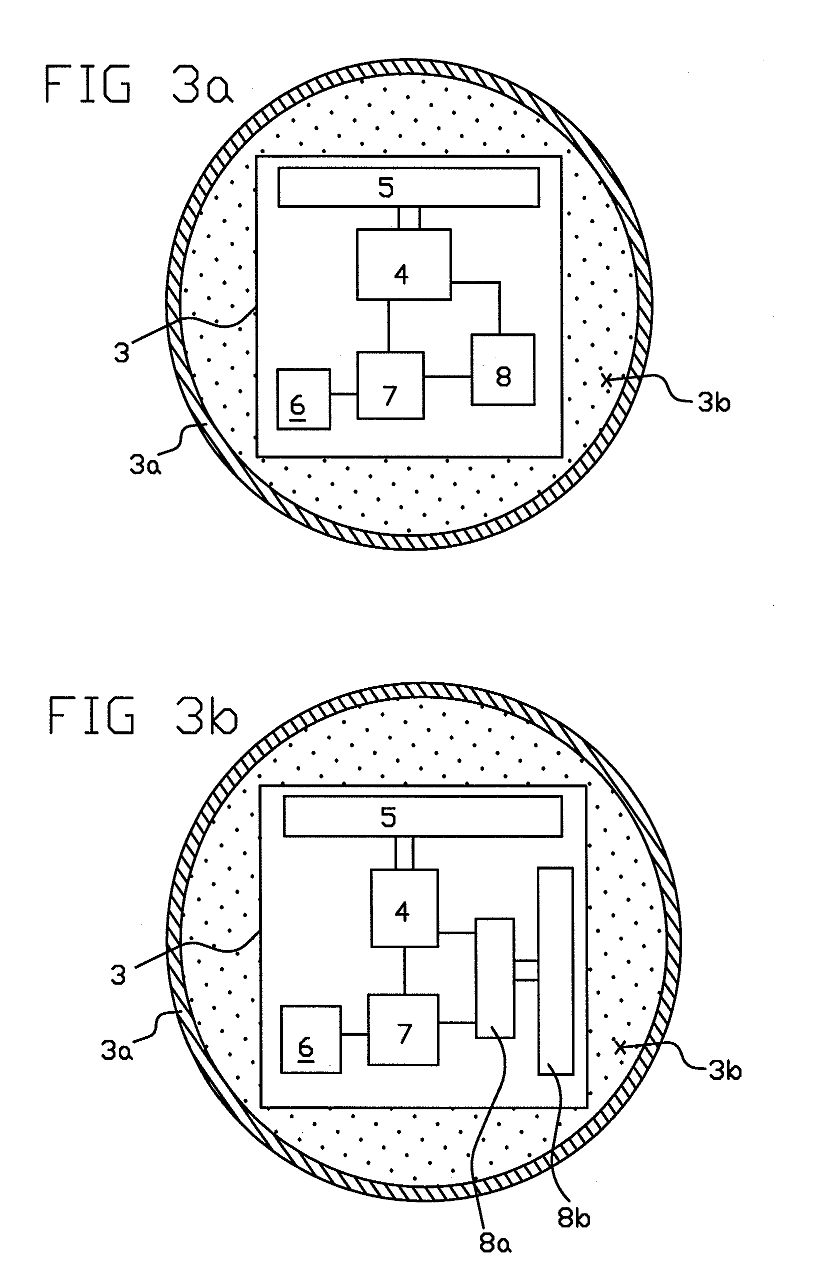
[0055]According to FIG. 3a, the tag energy source 8 comprises an energy storage device, such as a battery.

second embodiment

[0056]According to FIG. 3b, the tag antenna is a tag communication antenna 5 which preferably comprises a first elongated ferrite core for enhanced data communications. In this embodiment, the aforesaid tag energy source 8 comprises a) a tag power antenna 8b (preferably comprising a second elongated ferrite core, oriented substantially orthogonally to the first elongated ferrite core) operable to pick up electric energy induced by an applied varying electric field, and b) an energy storage device 8a (such as a capacitor or chargeable battery) connected to receive charging energy from the tag power antenna 8b. Preferably, the tag communication antenna 5 is tuned to maximize signal strength at a frequency f(com) that is distinct from (e.g. is an integer multiple of) the frequency f(power) to which the tag power antenna 8b is tuned. Neither f(com) nor f(power) exceed 1.0 megahertz. For example, when f(power)=64 hertz, then f(com) could be 128 hertz. According to this embodiment, reader...


PUM


Abstract

Identification and tracking of hollow pipes at a site where the hollow pipes are to be stored or interconnected, such as an oil drilling site where the aforesaid hollow pipes are to be connected and the drillstring of pipes is to be inserted into a drilled hole on solid ground or under a deepsea drilling platform is achieved. Each hollow pipe is provided with a low frequency radio frequency identification (RFID) tag attached to the pipe's outer surface. The RFID tag is operable at a low radio frequency not exceeding 1.0 megahertz and may be disposed within a recess in the pipe's outer surface. A tracking system provides communication be the tags and a reader.

Description

CROSS-REFERENCE TO RELATED APPLICATIONS[0001]The present application claims the benefit of from U.S. Provisional Application No. ______, filed on Mar. 3, 2010, and is a continuation-in-part of U.S. application Ser. No. 11 / 677,037 filed Feb. 20, 2007, which is a continuation-in-part of U.S. application Ser. No. 11 / 461,443 filed Jul. 31, 2006, now U.S. Pat. No. 7,277,014, which is a continuation-in-part of U.S. application Ser. No. 11 / 276,216 filed Feb. 17, 2006, now U.S. Pat. No. 7,164,359, which is a continuation of U.S. application Ser. No. 10 / 820,366 filed Apr. 8, 2004, now U.S. Pat. No. 7,049,963, which claims the benefit of U.S. application No. 60 / 461,562 filed Apr. 9, 2003. This application is also a continuation in part of U.S. patent application Ser. No. 11 / 639,857, filed Dec. 15, 2006. All of these applications are incorporated herein by reference for all purposes.FIELD OF THE INVENTION[0002]This invention relates to a trackable pipe, such as a tubular pipe used in oil drill...

Claims


Application Information

Patent Timeline
Patent Type & Authority Applications(United States)
IPC IPC(8): G08B1/08
CPCG06Q10/08G06Q10/087G07C9/00111G06Q50/30G06Q50/02G07C9/28
Inventor STEVENS, JOHN K.AUGUST, M. JASONWATERHOUSE, PAUL
Owner VISIBLE ASSET INC
Why Eureka
Try Eureka