
Liquid ejecting apparatus and control method of the same

Active Publication Date: 2010-09-30
SEIKO EPSON CORP
View PDF4 Cites 13 Cited by
  • Summary
  • Abstract
  • Description
  • Claims
  • Application Information

AI Technical Summary

Benefits of technology

[0009]It is an advantage of some aspects of the invention to provide a liquid ejecting apparatus capable of ejecting a highly-viscous liquid in a stable manner by controlling residual vibrations following the ejection of the liquid, and a control method for a liquid ejecting apparatus.
[0011]According to this aspect, vibrations of a phase inverted relative to residual vibrations arising in the liquid within the pressurizing chamber due to the ejection of the liquid may be imparted, thereby retracting the meniscus toward the pressurizing chamber and suppressing the growth of tails accompanying the liquid ejected by the ejection driving pulse. Accordingly, the phenomenon in which tails extend from the posterior portion of ejected liquid may be suppressed when ejecting a liquid of a comparatively high viscosity (a highly-viscous liquid). This makes it possible to prevent the liquid from separating into multiple parts and impacting upon the impact target, or in other words, makes it possible to prevent dot separation. Furthermore, because the residual vibrations are suppressed, the residual vibrations may also be suppressed from imparting negative influence on the ejection operations of the next ejection cycle (changes in the ink amount, flight speed, and so on). Further still, because it is unnecessary to provide a vibration dampening period for dampening the residual vibrations following the non-ejection driving pulse, the ejection cycle may be shortened by that amount, thereby making it possible to suppress a drop in the driving frequency.
[0013]According to this configuration, the voltage difference of the expansion element in the non-ejection driving pulse is set at less than or equal to 40% of the potential difference between the minimum potential and the maximum potential of the ejection driving pulse, and thus it is possible to suppress an increase in the residual vibrations caused by the expansion element in the non-ejection driving pulse, thereby making it possible to ensure the stability of the meniscus.

Problems solved by technology

However, increasing the pressure change causes the liquid to travel at a higher speed, which tends to cause the occurrence of a phenomenon in which the posterior portion of the liquid extends in a tail-like form.
Thus there has been a risk of this tail-like portion separating and jumping away from the primary droplet and failing to impact in the proper location (the desired location) on the impact target.
For example, in ink jet printers, there has been a problem in that the tail-like portion has turned to mist, shifting from the proper location and then impacting, resulting in separated dots and thus leading to a degradation in image quality.
In particular, with highly-viscous liquids, the tail-like portion separates into several parts, and those multiple separated parts (satellite ink droplets, or mist) have been the cause of a dramatic drop in image quality.
However, there is a risk that residual vibrations occurring in the ink within the pressurizing chamber due to the application of the non-ejection driving pulse to the pressurizing element will negatively influence the ejecting operations in the next ejection cycle (that is, cause changes in the ink amount, flight speed, and so on).
There has thus been a problem that the overall ejection cycle has been lengthened by the vibration dampening period, resulting in a drop in the drive frequency.

Method used


Image

  • Liquid ejecting apparatus and control method of the same
  • Liquid ejecting apparatus and control method of the same
  • Liquid ejecting apparatus and control method of the same

Examples


Embodiment Construction

[0021]Hereinafter, embodiments of the invention will be described with reference to the appended drawings. Although various limitations are made in the embodiments described hereinafter in order to illustrate a specific preferred example of the invention, it should be noted that the scope of the invention is not intended to be limited to these embodiments unless such limitations are explicitly mentioned hereinafter. An ink jet recording apparatus (referred to as a printer) will be given hereinafter as an example of a liquid ejecting apparatus according to the invention.

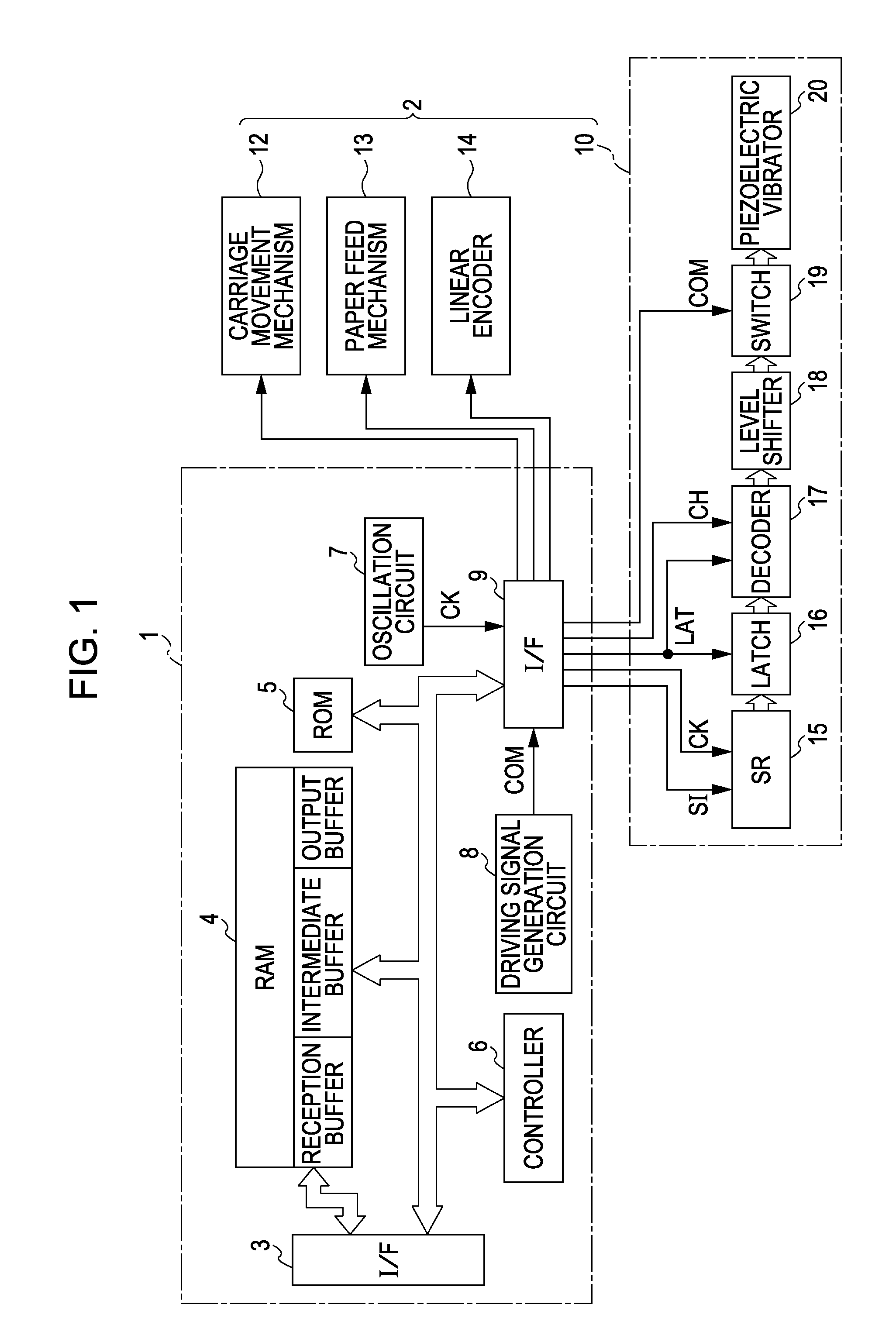
[0022]FIG. 1 is a block diagram illustrating the electrical configuration of a printer. This printer is broadly configured of a printer controller 1 and a print engine 2. The printer controller 1 includes an external interface (external I / F) 3 that exchanges data with an external device such as a host computer or the like, a RAM 4 that stores various data and the like, a ROM 5 that stores control routines and the like...


PUM


Abstract

A liquid ejecting apparatus includes a liquid ejecting head having a nozzle, a pressurizing chamber that communicates with the nozzle, and a pressurizing element that causes a pressure change in liquid within the pressurizing chamber, the liquid ejecting head being capable of ejecting liquid from the nozzle by operating the pressurizing element; and a driving signal generation unit that generates a driving signal including a driving pulse that drives the pressurizing element. The driving signal includes an ejection driving pulse that ejects a liquid droplet and a non-ejection driving pulse that drives the pressurizing element to a degree whereby a liquid droplet is not ejected. The ejection driving pulse is a pulse waveform having an expansion element that causes the pressurizing chamber to expand and retract a meniscus toward the pressurizing chamber and a constriction element that causes the pressurizing chamber expanded by the expansion element to constrict and push the meniscus in the direction of ejection. The non-ejection driving pulse is a pulse waveform having an expansion element that causes the pressurizing chamber to expand and retract the meniscus toward the pressurizing chamber, a holding element that holds the voltage at the end of the expansion element for a set amount of time, and a constriction element that causes the pressurizing chamber expanded by the expansion element to constrict and push the meniscus in the direction of ejection. When the length of time from the end of the constriction element in the ejection driving pulse to the beginning of the expansion element in the non-ejection driving pulse is taken as t, the lengths of time of the expansion element, holding element, and constriction element in the non-ejection driving pulse are taken as a, b, and c, respectively, and the inherent vibration cycle of the liquid within the pressurizing chamber is taken as Tc, t, a, b, and c are within the ranges defined by the following equations (1) through (3):Tc / 4≦t≦Tc / 2  (1)(5Tc / 8)−t≦a≦(3Tc / 4)−t  (2)b+c=Tc−t−a  (3)

Description

BACKGROUND[0001]1. Technical Field[0002]The present invention relates to a liquid ejecting apparatus such as an ink jet printer and a control method thereof, and particularly relates to a liquid ejecting apparatus that includes a liquid ejecting head in which a change in pressure is applied to a pressurizing chamber communicating with a nozzle, thereby causing liquid within the pressurizing chamber to be ejected from the nozzle, and to a control method for the apparatus.[0003]2. Related Art[0004]A liquid ejecting apparatus is an apparatus that includes a liquid ejecting head capable of ejecting a liquid, and that ejects various types of liquid from the liquid ejecting head. An image recording apparatus such as an ink jet printer (called simply a printer hereinafter) that is provided with an ink jet recording head (called simply a recording head hereinafter) as its liquid ejecting head and that records images by causing ink in liquid form to be ejected from a nozzle in the recording ...

Claims


Application Information

Patent Timeline
IPC IPC(8): B41J29/38
CPCB41J2/04581B41J2/04588B41J29/38B41J2/04596B41J2/04595
Inventor SUZUKI, YOSHIYUKI
Owner SEIKO EPSON CORP
Learn More