Head cleaning method and head cleaning apparatus

a cleaning method and cleaning method technology, applied in the direction of printing, inking apparatus, etc., can solve the problem of creating wiping traces on the nozzle surface, and achieve the effect of improving the selection range of the ink absorbing body, easing the conditions relating, and increasing the selection range of the wiping member used

Active Publication Date: 2010-09-30
FUJIFILM CORP
View PDF1 Cites 74 Cited by
  • Summary
  • Abstract
  • Description
  • Claims
  • Application Information

AI Technical Summary

Benefits of technology

[0081]According to this aspect, the nozzle surface of the head is wiped and cleaned by pressing and abutting a wiping member against the nozzle surface of the head and sliding a wiping member over the nozzle surface of the head while suctioning the wiping member via a suction hole. In this, the wiping member is suctioned via the suction hole by setting a suctioning force which does not give rise to wiping traces or wiping omissions on the nozzle surface after wiping. Accordingly, it is possible to clean the nozzle surface without the occurrence of wiping traces or wiping omissions in a single wiping action. Furthermore, by this means, it is also possible to ease the conditions relating to the wiping member which can be used, and therefore the range of selection of the wipi...

Problems solved by technology

On the other hand, if the nozzle surface is wiped and cleaned using a liquid absorbing body having a high liq...

Method used


Image

  • Head cleaning method and head cleaning apparatus
  • Head cleaning method and head cleaning apparatus
  • Head cleaning method and head cleaning apparatus

Examples


second embodiment

of Head Cleaner of Second Mode

[0356]FIG. 20 is a plan diagram of a second embodiment of a head cleaner according to the second mode, FIG. 21 is a side view diagram of a second embodiment of the head cleaner according to the second mode, and FIG. 22 is a cross-sectional diagram along 22-22 in FIG. 21.

[0357]As shown in FIG. 20 to FIG. 22, the head cleaners 1200 (1200C, 1200M, 1200Y and 1200K) according to the present embodiment each comprise two wiping webs 110L and 110R having different liquid absorption capabilities and wipe and clean the nozzle surface of the heads by switching the wiping webs used in a first action and a second action. In other words, the nozzle surface of each head is wiped by using a first wiping web 110L having a high liquid absorption capability (a wiping web having high liquid absorption capability sufficient to avoid the occurrence of wiping omissions when the nozzle surface of the head is wiped) in a first action (first cleaning step), and the nozzle surfac...

third embodiment

of Head Cleaner of Second Mode

[0407]FIG. 24 is a front view diagram of a third embodiment of a head cleaner according to the second mode and FIG. 25 is a plan diagram of the third embodiment of the head cleaner according to the second mode.

[0408]As shown in FIG. 24 and FIG. 25, the head cleaners 300 (300C, 300M, 300Y and 300K) according to the present embodiment each comprise two wiping webs 110M and 110N having different liquid absorption capabilities and wipe and clean the nozzle surface of the heads by switching the wiping webs used in a first action and a second action, in a similar fashion to the head cleaners 1200 of the second embodiment of the second mode which are described above.

[0409]The head cleaners 300 according to the present embodiment differ from the head cleaners 1200 according to the second embodiment of the second mode described above in that the wiping webs 110M and 110M are disposed in a forward / rearward relationship in the direction of movement of the heads 16...

fourth embodiment

of Head Cleaner of Second Mode

[0452]FIG. 26 is a front view diagram of a fourth embodiment of a head cleaner according to the second mode.

[0453]The head cleaner 400 (400C, 400M, 400Y and 400K) according to the present embodiment also wipes and cleans the nozzle surface of the head in two separate actions, by switching the liquid absorption capability of the wiping web.

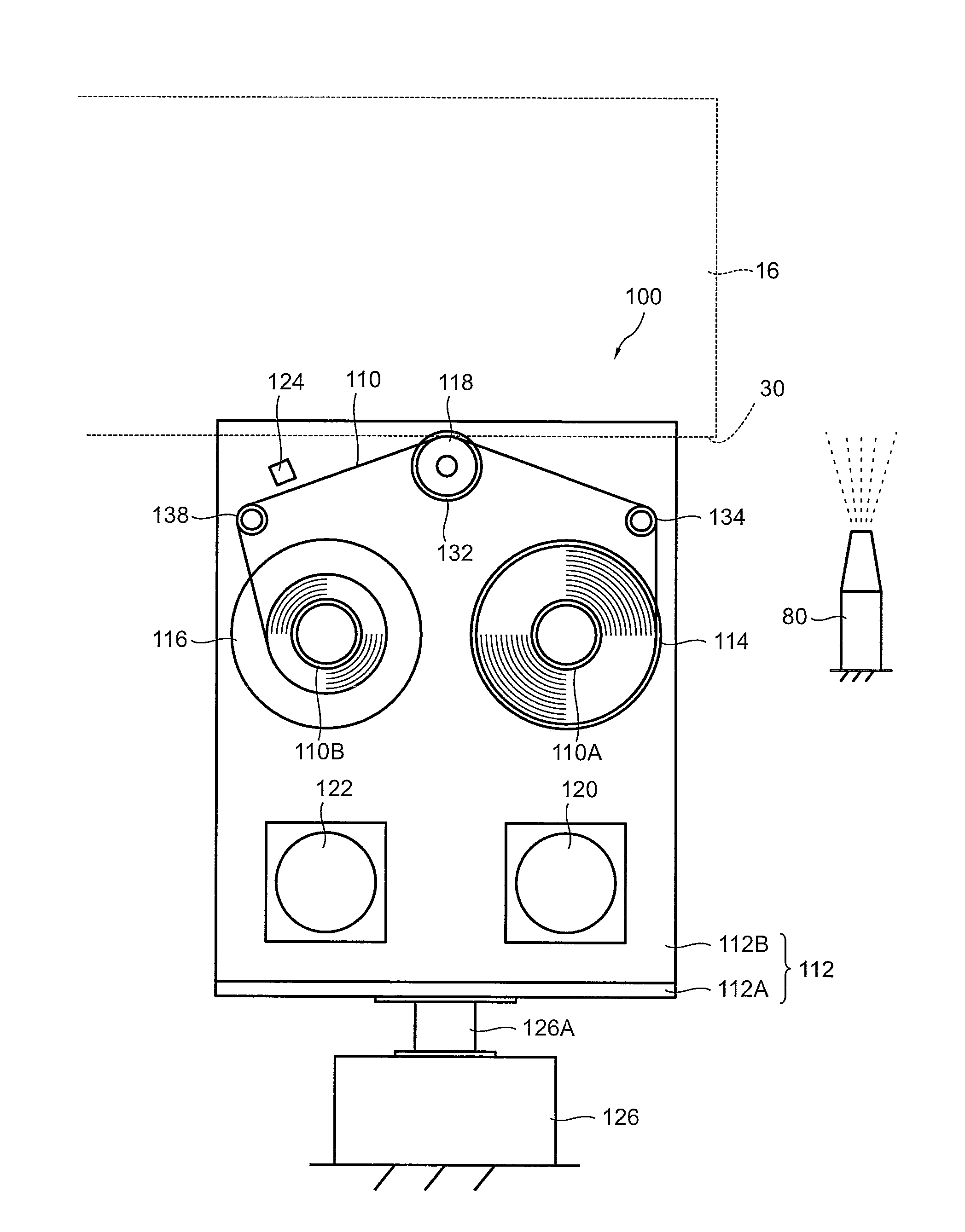
[0454]The head cleaner 400 according to the present embodiment switches the liquid absorption capability of the wiping web by depositing liquid onto the wiping web. For this purpose, as shown in FIG. 26, the head cleaner 400 according to the present embodiment comprises a liquid deposition nozzle 410 for depositing cleaning liquid onto the wiping web 402. Apart from the fact that this liquid deposition nozzle 410 is provided, this head cleaner is the same as the head cleaner 100 according to the first embodiment of the second mode which is described above. Consequently, only the liquid deposition nozzle 410 is describe...


PUM


Abstract

A head cleaning method of wiping and cleaning a nozzle surface of a head with a band-shaped liquid absorbing body by, while pressing and abutting a pressing member on which the liquid absorbing body that travels is wrapped against the nozzle surface of the head, sliding the pressing member over the nozzle surface of the head, includes: a first cleaning step of wiping and cleaning the nozzle surface of the head with a non-wet region of the liquid absorbing body; a wet region forming step of forming a wet region on the liquid absorbing body; and a second cleaning step of wiping and cleaning the nozzle surface of the head with the wet region of the liquid absorbing body.

Description

BACKGROUND OF THE INVENTION[0001]1. Field of the Invention[0002]The present invention relates to a head cleaning method and a head cleaning apparatus, and more particularly, to a head cleaning method and a head cleaning apparatus for wiping and cleaning a nozzle surface with a liquid absorbing body.[0003]2. Description of the Related Art[0004]In an inkjet recording apparatus which carries out image recording by ejecting very fine ink droplets from nozzles, if a recording operation is performed continuously, then ink in the form of a mist ejected from the nozzles adheres to and accumulates on the vicinity of the nozzles, and can give rise to nozzle blockages. Consequently, in an inkjet recording apparatus, cleaning of the nozzle surface is carried out periodically.[0005]Japanese Patent Application Publication No. 2006-205712 discloses, as a method for cleaning the nozzle surface, a method in which the nozzle surface is wiped with a blade and then the nozzle surface is further wiped w...

Claims


Application Information

Patent Timeline
IPC IPC(8): B41J2/165
CPCB41J2/16535B41J2202/21B41J2/16585B41J2002/1655
Inventor INOUE, HIROSHI
Owner FUJIFILM CORP
Why Eureka
Try Eureka