
Image processing apparatus and its image processing method

a technology of image communication apparatus and image processing method, which is applied in the field of image processing apparatus, can solve the problems of document 1 not being able to accommodate the image processing method of the image communication apparatus, and achieve the effect of minimizing the need for buffer capacity

Inactive Publication Date: 2010-09-30
PANASONIC CORP
View PDF12 Cites 4 Cited by
  • Summary
  • Abstract
  • Description
  • Claims
  • Application Information

AI Technical Summary

Benefits of technology

[0012]An object of the present invention is therefore to provide an image processing apparatus and its image processing method that can reduce the buffer capacity which is necessary in rotating image data by an arbitrary angle.
[0014]According to the invention, it suffices that the rotated image buffering section for storing processing blocks to perform rotation has a capacity that corresponds to three processing blocks E for each band, extending in the reference direction, of image data. Therefore, the necessary buffer capacity can be minimized. That is, the invention can save the memory capacity that is required in rotating image data by an arbitrary angle.
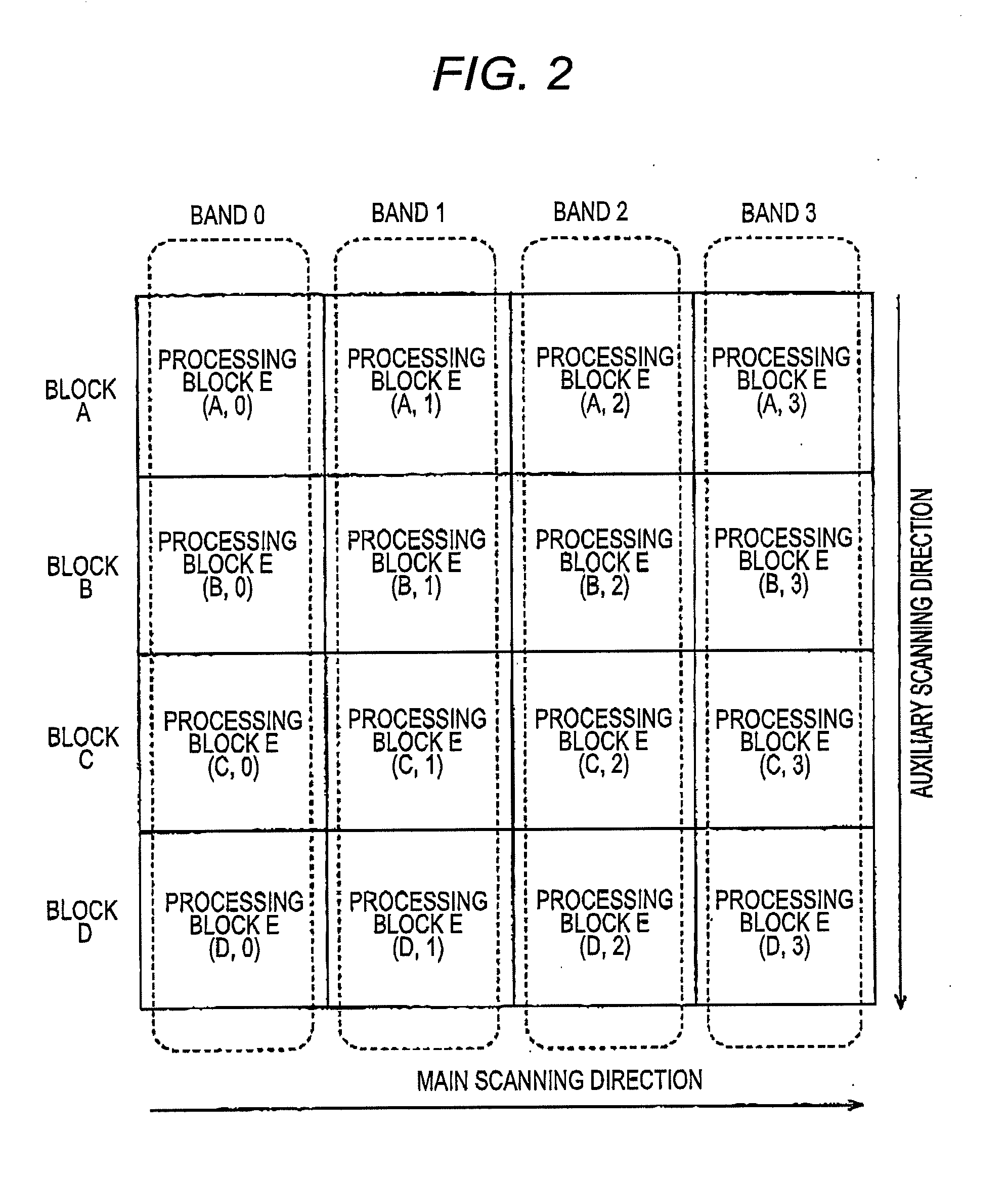
[0015]A first aspect of the invention provides an image processing apparatus comprising a storage section for storing image data; a storage managing section for managing the image data in the form of plural processing blocks that are arranged in a vertical direction and a horizontal direction, and storing at least part of the processing blocks in the storage section in such a manner that each processing block is accessible; a block data reading section for reading, as processing subject blocks, processing blocks that overlap with a rectangular area inclined with respect to the image data by a certain angle and in which at most three processing blocks are arranged in a reference direction which is a vertical direction or a horizontal direction, from the storage section for each band of processing blocks arranged in the reference direction; a rotated image buffering section for storing the read-out processing subject blocks, the rotated image buffering section having a capacity corresponding to three processing blocks for each band of processing blocks arranged in the reference direction; and a block rotating section for rotating the processing subject blocks that are read out by the block data reading section by a specified angle while maintaining positional relationships between the processing subject blocks, and storing rotated processing subject blocks in the rotated image buffering section. In this aspect of the invention, to cut out and rotate back a rectangular area that is inclined with respect to the area of image data by a certain angle, the block data reading section reads out, as processing subject blocks, for each band of processing blocks arranged in the reference direction, processing blocks that overlap with the inclined rectangular area and in which at most three processing blocks are arranged in the reference direction. As a result, the rotation processing can be performed by processing a smallest amount of data. It suffices that the rotated image buffering section for storing processing blocks to perform rotation has a capacity that corresponds to three processing blocks for each band, extending in the reference direction. Therefore, the necessary buffer capacity can be minimized.
[0019]A fifth aspect of the invention provides an image processing method which is characterized by comprising a storage managing step of managing image data in the form of plural processing blocks that are arranged in a vertical direction and a horizontal direction, and storing at least part of the processing blocks in storage section in such a manner that each processing block is accessible; a block data reading step of reading, as processing subject blocks, processing blocks that overlap with a rectangular area inclined with respect to the image data by a certain angle and in which at most three processing blocks are arranged in a reference direction which is a vertical direction or a horizontal direction, from the storage section for each band of processing blocks arranged in the reference direction; and a block rotating step of rotating the read-out processing subject blocks by a specified angle while maintaining positional relationships between the processing subject blocks, and storing rotated processing subject blocks in a rotated image buffering section for storing the read-out processing subject blocks which has a capacity corresponding to three processing blocks for each band of processing blocks arranged in the reference direction. In this aspect of the invention, to cut out and rotate back a rectangular area that is inclined with respect to the area of image data by a certain angle, processing blocks that overlap with the inclined rectangular area and in which at most three processing blocks are arranged in the reference direction are read out as processing subject blocks for each band of processing blocks arranged in the reference direction. As a result, the rotation processing can be performed by processing a smallest amount of data. It suffices that the rotated image buffering section for storing processing blocks to perform rotation has a capacity that corresponds to three processing blocks for each band extending in the reference direction. Therefore, the necessary buffer capacity can be minimized.

Problems solved by technology

However, the image processing method of the image communication apparatus disclosed in Patent document 1 cannot accommodate a case of rotating image data that is inclined by an arbitrary angle other than 90°, 180°, and 270° with respect to a reference direction.

Method used


Image

  • Image processing apparatus and its image processing method
  • Image processing apparatus and its image processing method
  • Image processing apparatus and its image processing method

Examples


embodiment

[0031]An image processing apparatus and its image processing method according to an embodiment of the invention will be hereinafter described with reference to the drawings using a scanner as an example.

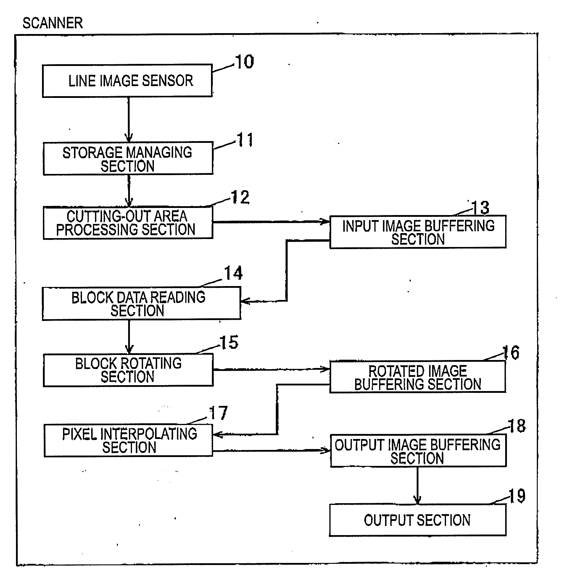
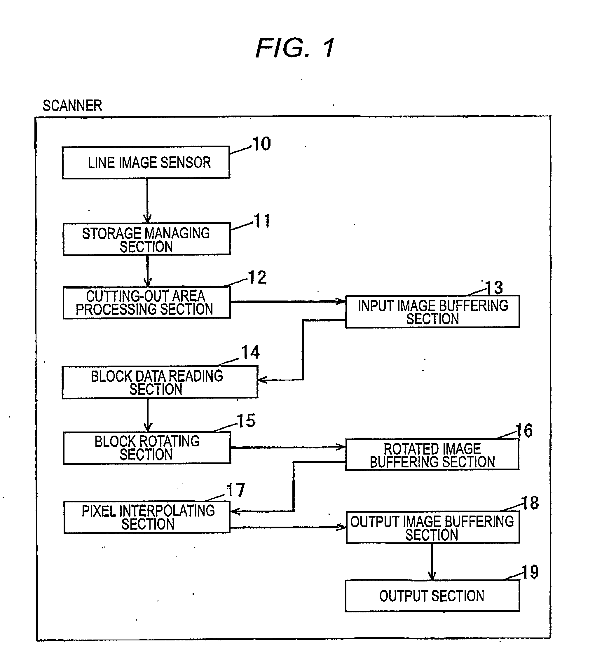
[0032]FIG. 1 is a block diagram showing the configuration of the image processing apparatus according to the embodiment of the invention.

[0033]As shown in FIG. 1, the scanner according to the embodiment of the invention is provided with a line image sensor 10, a storage managing section 11, a cutting-out area processing section 12, a input image buffering section 13, a block data reading section 14, a block rotating section 15, a rotated image buffering section 16, a pixel interpolating section 17, an output image buffering section 18, and an output section 19.

[0034]Being a general solid-state imaging device such as an optical reduction type CCD (charge-coupled device) or a contact sensor type CIS (contact image sensor), the line image sensor 10 can read a document image in full-colo...


PUM


Abstract

A scanner is equipped with an input image buffering section 13 for storing read-out image data; a storage managing section 11 for managing the image data in the form of processing blocks that are arranged in the vertical direction and the horizontal direction; a block data reading section 14 for reading, as processing subject blocks, processing blocks each of which overlaps with a divisional cuffing-out block of a document image which is inclined with respect to the image data by a certain angle, from the input image buffering section 13 for each band of processing blocks arranged in the auxiliary scanning direction; and a block rotating section 15 for rotating the processing subject blocks while maintaining positional relationships between them, and storing rotated processing subject blocks in a rotated image buffering section which has a capacity corresponding to three processing blocks for each band of processing blocks arranged in the auxiliary scanning direction.

Description

BACKGROUND[0001]1. Field of the Invention[0002]The present invention relates to an image processing apparatus that reads a document image with an image sensor and storing resulting image data in a storage section, as well as to its image processing method.[0003]2. Description of the Related Art[0004]When plural pages of a document are supplied to a reading device with an automatic sheet feeder and read by the reading device, there may occur an event that a document page is supplied to the reading device obliquely. In this case, a document image portion contained in image data obtained by reading such a document page is inclined and hence it is necessary to perform a correction of rotating the document image portion into a non-inclined one.[0005]Where the maximum readable document size of a reading device is the A3 size and a document to be read has the A4 size, document pages can be read irrespective of whether they are oriented vertically or horizontally. In such a case, it may be ...

Claims


Application Information

Patent Timeline
IPC IPC(8): G06F15/00
CPCH04N1/3878G06T3/602
Inventor FUKAYA, TERUYUKI
Owner PANASONIC CORP
Learn More