Image recognition device and image recognition method

a technology of image recognition and image, applied in the field of image recognition device and image recognition method, can solve problems such as conventional position detection devices, and achieve the effect of facilitating the extraction of captured images

Inactive Publication Date: 2010-09-30
SHIMANE PREFECTURAL GOVERNMENT MATSUE
View PDF7 Cites 37 Cited by
  • Summary
  • Abstract
  • Description
  • Claims
  • Application Information

AI Technical Summary

Benefits of technology

[0009]The invention according to claim 2 is configured such that the three-dimensional measurement reference has a marker on a surface thereof facing the imaging means so as to make extraction from the captured image easier in the image recognition device according to claim 1.

Problems solved by technology

However, conventional position detection devices have a problem that they require calibration every shooting, installation work of their ancillary equipments, and a complicated work such as putting on and taking off a special marker to the object.

Method used


Image

  • Image recognition device and image recognition method
  • Image recognition device and image recognition method
  • Image recognition device and image recognition method

Examples


first embodiment

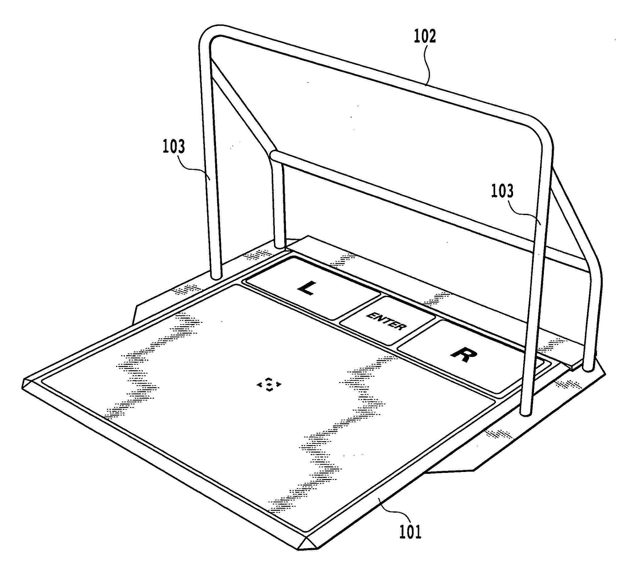
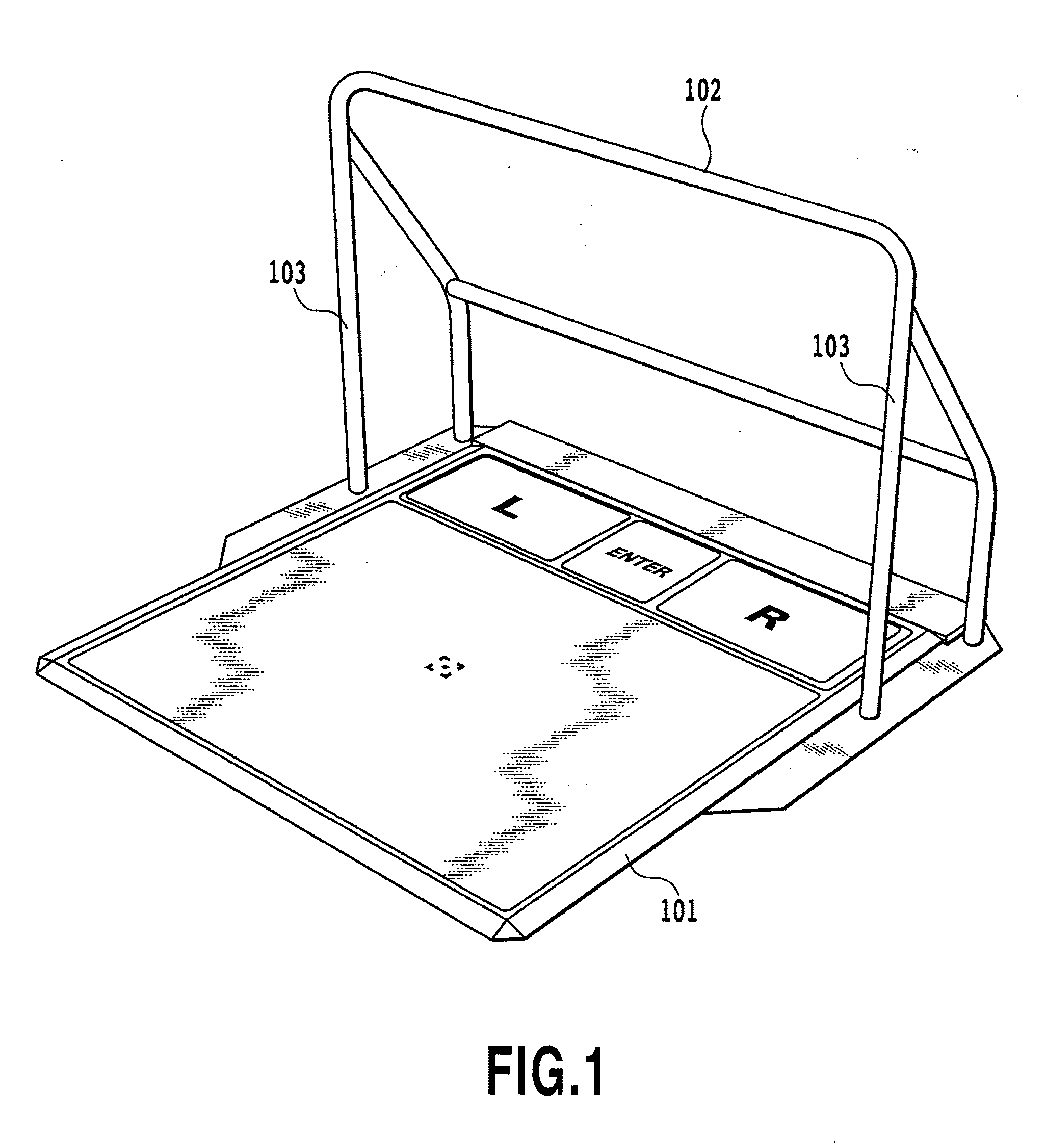
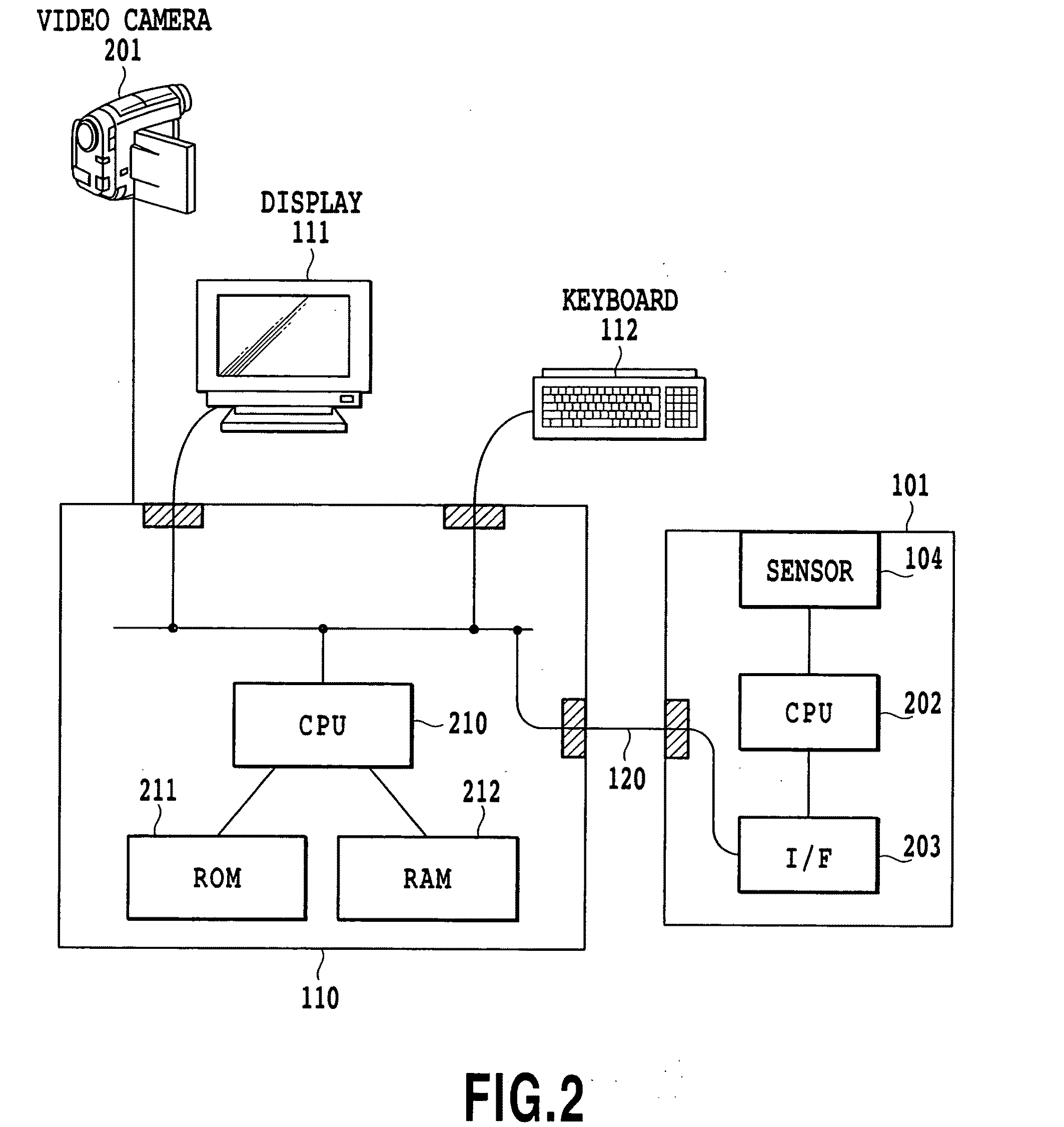
[0046]FIG. 1 is a diagram illustrating one example of an exercise assist device with a horizontal bar according to the present embodiment, among an image recognition device illustrated in FIG. 7. An exercise assist device 101 according to the present embodiment includes a horizontal bar 102, a bar support 103 to support the horizontal bar 102, and a floor mat 104 provided on a surface of a body thereof. An operator does exercise or plays a game on the floor mat 104. Examples of exercise include jogging illustrated in FIGS. 18 and 19. The operator does exercise while watching a monitor 701. A video camera 201 and the like as an imaging means is provided on the top of the monitor 701, as illustrated in FIG. 7 and can capture the operator, horizontal bar 102 and bar support 103 in the same image. As described later, since the horizontal bar 102 and bar support 103 are captured together with the operator in the same image, they become a three-dimensional measurement reference, thereby e...

second embodiment

[0060]Here will be described an example according to the present embodiment. Basically in addition to a system structure of the aforementioned first embodiment, a floor mat sensor is used as a floor mat of the exercise assist device 101 and the exercise assist device 101 is used as a device for inputting data to the computer 110 and the like. Needless to say, an application example combined with the aforementioned first embodiment can also be implemented in the present embodiment. According to the present embodiment, the exercise assist device 101 has the floor mat 104 on the surface of the body thereof. When a predetermined area of the floor mat 104 is stepped on, the floor mat 104 outputs data corresponding to the stepped-on position. As described later, when the operator moves his / her foot, the horizontal bar 102 supports the operator and also limits the moving area of the operator thereby to limit the movement of the foot so as to allow for a stable data input by the foot.

[0061]...

third embodiment

[0075]According to the present embodiment, in addition to the aforementioned second embodiment, the floor mat can perform various types of processing on the basis of pressure information of the stepped-on position. In other words, since the floor mat according to the present embodiment uses an electromagnetic guidance pressure distribution sensor having a structure illustrated in FIG. 10, the exercise assist device according to the present embodiment performs various types of processing such as specifying the center of gravity of the operator on the floor mat on the basis of the outputted pressure information of each stepped-on position. The exercise assist device of the present embodiment has the same system structure as that of the first embodiment except that in the present embodiment the floor mat is limited to the pressure distribution sensor. According to the present embodiment, the floor mat can be used as a device for inputting various information such that, for example, as ...


PUM


Abstract

The present invention is aimed at detecting an operator's height and position of each body part with a certain range of accuracy, which is used for calculation of a BMI value or operation of a game. An exercise assist device (101) is provided with a horizontal bar (102), a bar support (103) to support the bar, and a floor mat (104) on a surface of its body. A video camera (201) is mounted on the top of a monitor (701) as illustrated, for example, in FIG. 7 and captures the operator as well as the horizontal bar (102) and bar support (103) in one image. Since the horizontal bar (102) and bar support (103) together with the operator are captured in one image, they become a three-dimensional measurement reference, so that the operator's height can be calculated from the captured image.

Description

TECHNICAL FIELD[0001]The present invention relates to an image recognition device and an image recognition method, and more particularly, to an image recognition device and an image recognition method to measure an object to be measured on the basis of an image captured by a video camera and the like.BACKGROUND ART[0002]Recently, people have been health-conscious and various exercise assist devices have been developed in recent years. Meanwhile, metabolic syndrome has been highlighted as a potential risk to cause adult illnesses and the body-mass index (BMI) value has been emphasized as its reference value. The BMI value is the index that is calculated based on the relationship between body weight and body height and indicates the degree of obesity. When the body height is t (m) and body weight is w (kg), BMI is represented by the equation BMI=w / t2. An operator doing exercise with the use of the aforementioned exercise assist device measures his / her body weight and height after exer...

Claims


Application Information

Patent Timeline
Patent Type & Authority Applications(United States)
IPC IPC(8): G06K9/46G01B11/00
CPCA61B5/1072A63B6/00A63B24/0006A63B69/0035A63B2024/0012A63B2071/0638A63B2220/833A63B2208/0204A63B2220/13A63B2220/52A63B2220/56A63B2220/806A63B2071/0647
Inventor IZUMI, KENJI
Owner SHIMANE PREFECTURAL GOVERNMENT MATSUE
Why Eureka
Try Eureka