

Module for a Modular Microfluidic System
- Summary
- Abstract
- Description
- Claims
- Application Information
AI Technical Summary
Benefits of technology
Problems solved by technology
Method used
Image

Examples
Embodiment Construction
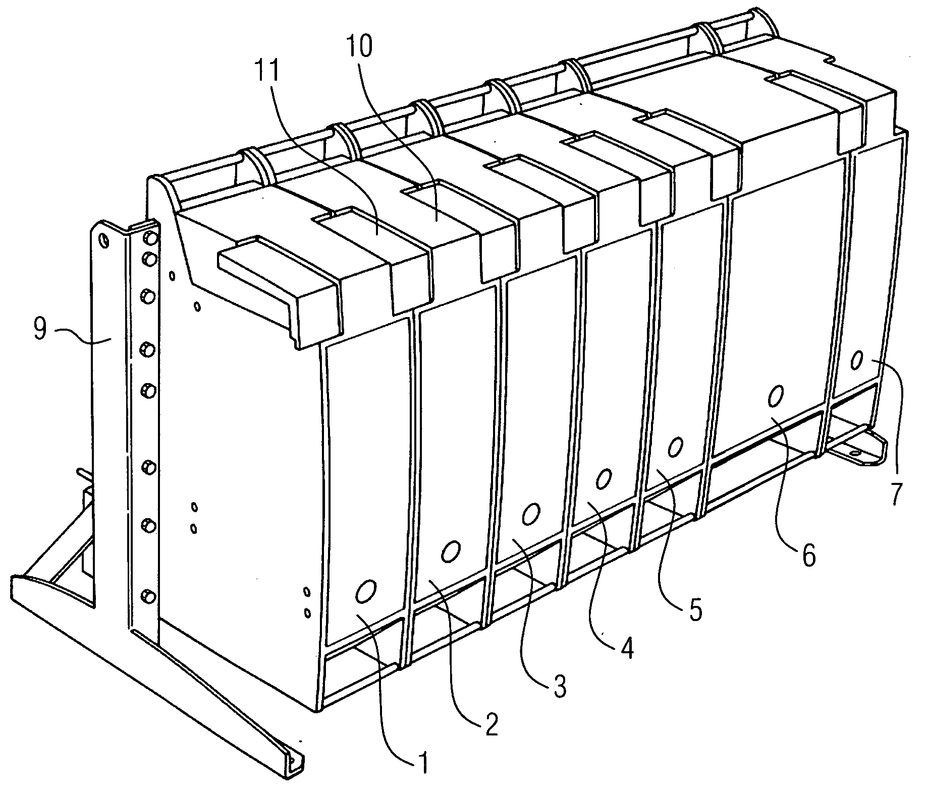
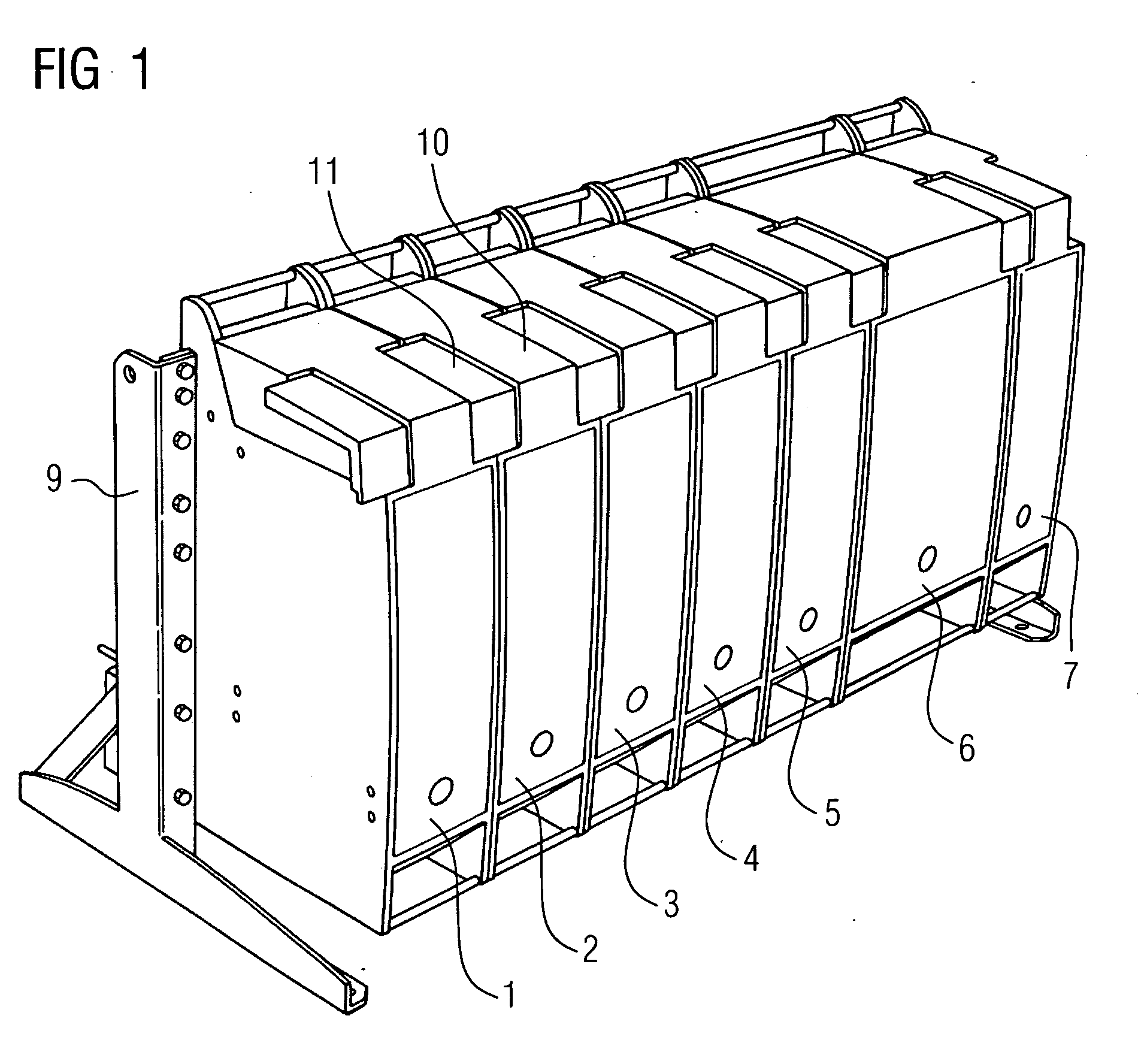
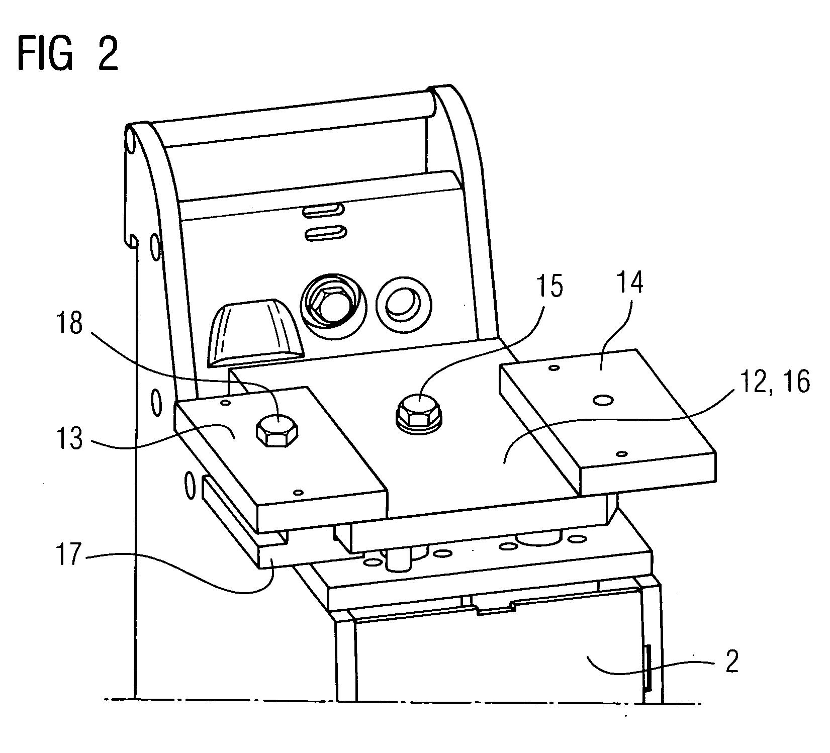
[0025]FIG. 1 shows a microfluidic system comprising modules 1 to 7 which are arranged adjacent to one another in a row and are held at the rear on a carrier frame 9. In this array the modules 1 and 7 form the end modules, i.e. the start and end modules, of the microfluidic system. Each module 1 to 7 contains a microfluidic part and an associated electrical control unit. The control units of the different modules are interconnected via an electrical line bus and the microfluidic parts via a fluid bus. The electrical line bus runs in the carrier frame 9, the modules 1 to 7 being removably connected to the line bus via rear-side plug-in connectors. The fluid bus is formed by connecting parts which contain connection channels and fluidically connect the microfluidic parts of respectively adjacent modules 1 to 7 to one another. The microfluidic parts are disposed in the region of the top sides of the modules and during normal operation of the microfluidic system are covered by protective...
PUM
 Abstract
Description
Claims
Application Information