Road Surface Condition Identification Based on Statistical Pattern Recognition

a technology of condition identification and road surface, applied in the direction of brake systems, process and machine control, instruments, etc., can solve the problems of not being practical, approach can be rather complicated, approach typically requires extra sensors, etc., and achieve the effect of minimizing cost and complexities

Active Publication Date: 2010-09-30
GM GLOBAL TECH OPERATIONS LLC
View PDF6 Cites 12 Cited by
  • Summary
  • Abstract
  • Description
  • Claims
  • Application Information

AI Technical Summary

Benefits of technology

[0003]An advantage of an embodiment of the invention is the use of a statistical pattern recognition technique which estimates and identifies an adhesive condition of a road surface based on one of a plurality of pre-classified road surface adhesive categories. The system estimates the adhesive condition of the road from a plurality of pre-classified road surface categories while driving under any driving maneuvers including normal driving maneuvers and while minimizing the cost and complexities arising from additional hardware and sensors employed with other systems.

Problems solved by technology

However, this approach can be rather complicated since the frictional characteristics of the detected surfaces are largely dependent on a combination of surface pattern, strength, and elasticity, and even surface temperature, in addition to extra cost on the sensors and processors.
But this approach typically requires evasive maneuvers so that tire operates under nonlinear or near-limit region.
Therefore, it is often not very practical since many active safety and driver-assist features mainly operate under normal driving maneuvers that do not generate the needed large excitation for the tire to operate in nonlinear or near limit region.
In addition, this approach typically requires extra sensors, such as corner force measurement.

Method used


Image

  • Road Surface Condition Identification Based on Statistical Pattern Recognition
  • Road Surface Condition Identification Based on Statistical Pattern Recognition
  • Road Surface Condition Identification Based on Statistical Pattern Recognition

Examples


Embodiment Construction

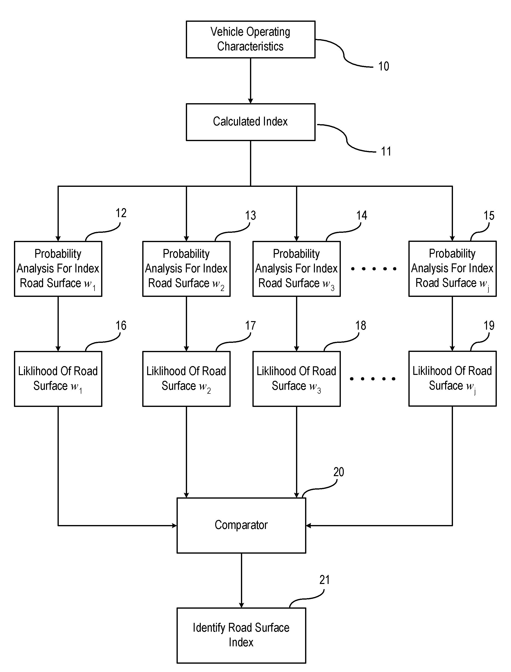
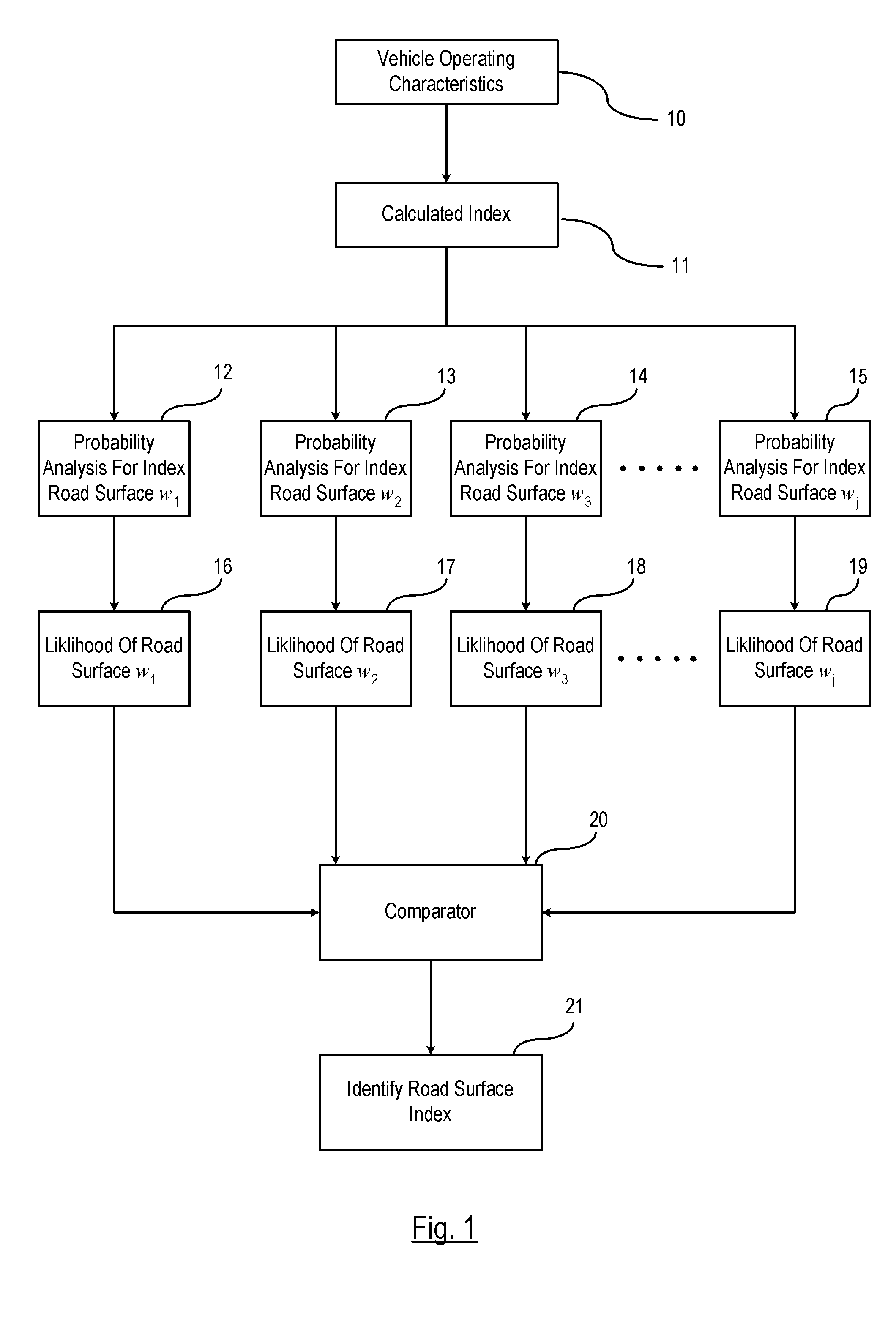
[0013]FIG. 1 is a broad flow diagram illustrating the road surface condition identification technique set forth in an embodiment of the invention. The road surface condition identification technique is conducted under normal driving conditions and identifies an adhesive effect of a road surface condition from one of a plurality of possible road surface adhesive conditions. It is understood that normal driving conditions include a vehicle driving along a road where no evasive maneuvers are required. The road surface condition identification technique estimates the adhesive effect of a road surface based on a determined index of each known road surface condition stored in memory and determines the likelihood of each adhesive effect being the condition of the current traveled road. It should be understood that the likelihood as described herein is only one embodiment of the invention and may be identified in more ways than described herein.

[0014]The estimation technique described herei...


PUM


Abstract

A method is provided for determining an adhesive condition of a surface of a vehicle road using a statistical pattern recognition technique. A plurality of probability distribution functions is provided representing respective adhesive effects between the vehicle tire of a driven vehicle and the vehicle road. An index is calculated which represents a vehicle understeer characteristic. Probability analysis is applied for each of the road surface adhesive conditions as a function of the index. Each probability analysis is recursively updated. A likelihood factor is determined for each road surface adhesive condition as a function of each respective recursively updated probability analysis. Each respective road surface adhesive condition has a respective likelihood factor that identifies the likelihood of the road surface having the respective adhesive condition as a function of the index. The identified adhesive condition of the road surface is input into a vehicle control process.

Description

BACKGROUND OF INVENTION[0001]An embodiment relates generally to identifying an adhesive effect of the road surface upon which a vehicle is traveling.[0002]Road surface condition identification has been mainly through remote-sensing measurement based on the reflection and absorption characteristics of the road pavement utilizing various methods including microwave and optical sensing techniques. However, this approach can be rather complicated since the frictional characteristics of the detected surfaces are largely dependent on a combination of surface pattern, strength, and elasticity, and even surface temperature, in addition to extra cost on the sensors and processors. On the other hand, road surface condition can also be inferred from the estimation of road surface friction. But this approach typically requires evasive maneuvers so that tire operates under nonlinear or near-limit region. Therefore, it is often not very practical since many active safety and driver-assist feature...

Claims


Application Information

Patent Timeline
Patent Type & Authority Applications(United States)
IPC IPC(8): G06F17/00
CPCB60W40/068
Inventor DENG, WEIWENZHAO, QINGRONG
Owner GM GLOBAL TECH OPERATIONS LLC
Why Eureka
Try Eureka