Driving force distribution device

Active Publication Date: 2010-10-07
HONDA MOTOR CO LTD
View PDF8 Cites 27 Cited by
  • Summary
  • Abstract
  • Description
  • Claims
  • Application Information

AI Technical Summary

Benefits of technology

[0009]The present invention is made in view of the above points, and it is an object of the present invention to provide a driving force distribution device for a four-wheel drive vehicle capable of making a gear portion of a rear differential small

Problems solved by technology

Thus, there has been a problem that it is hard to exert an effect obtained by controlling the yaw motion in such a situation.
However, the maximal driving torque of each of

Method used


Image

  • Driving force distribution device
  • Driving force distribution device
  • Driving force distribution device

Examples


Example

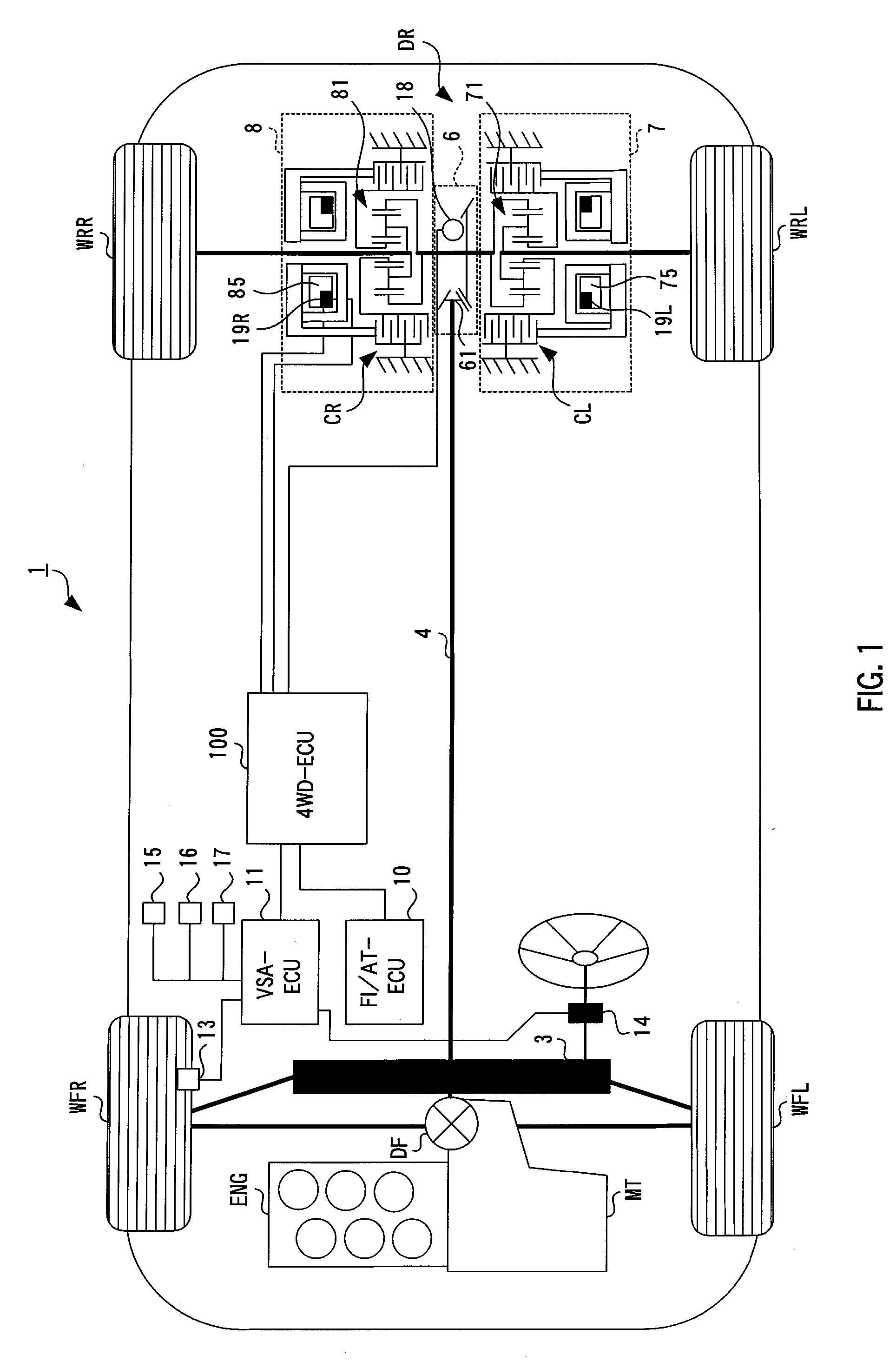
[0029]Hereinafter, a preferred embodiment of a driving force distribution device according to the present invention will be described in detail with reference to the appending drawings. The driving force distribution device according to the present invention is applied to, for example, a rear differential of a four-wheel drive vehicle, which distributes driving force between right and left rear wheels.

[0030]FIG. 1 is a schematic diagram showing a system summary of a four-wheel drive vehicle 1 to which the driving force distribution device according to the present invention is applied. As shown in FIG. 1, the four-wheel drive vehicle 1 includes: an engine ENG (driving source); a transmission MT; a front differential DF; a propeller shaft 4; and a rear differential DR. The engine ENG is transversely mounted in the front of a vehicle body. The transmission MT is integrally provided with the engine ENG. The front differential DF causes the transmission MT to be connected to front drive ...


PUM


Abstract

In the case where a difference between rotational speeds of right and left wheels detected by wheel speed sensors is less than a predetermined value, a right and left wheel power transmission control section distributes driving force between the right and left wheels so that a total value of the driving force of the right and left wheels does not exceed a limit value set up by a front and rear wheels power transmission control section. In the case where the difference between the rotational speeds of the right and left wheels is the predetermined value or more, the right and left wheel power transmission control section transmits the driving force up to a driving force upper limit for each wheel to the respective right and left rear wheels regardless of the total value of the driving force of the right and left rear wheels.

Description

CROSS-REFERENCE TO RELATED APPLICATION[0001]The present disclosure relates to subject matter contained in Japanese Patent Application No. 2009-090530, filed on Apr. 2, 2009, the disclosure of which is expressly incorporated herein by reference in its entirety.BACKGROUND OF THE INVENTION[0002]1. Field of the Invention[0003]The present invention relates to a driving force distribution device that distributes driving force between right and left wheels of front wheels or rear wheels in a four-wheel drive vehicle, and particularly, the present invention relates to a driving force distribution device capable of canceling a limitation on driving force to be transmitted to right and left wheels on the basis of a difference between wheel speeds of right and left wheels.[0004]2. Description of the Related Art[0005]Heretofore, in order to distribute driving force transmitted from an engine (driving source) via a propeller shaft to right and left rear wheels, a four-wheel drive vehicle provide...

Claims


Application Information

Patent Timeline
IPC IPC(8): B60K17/346
CPCB60K23/04
Inventor UEDA, MASAHIDEHARA, JIRO
Owner HONDA MOTOR CO LTD
Why Eureka
Try Eureka