
Backpack stool

Inactive Publication Date: 2010-10-07
POPESCU VIRGIL
View PDF18 Cites 16 Cited by
  • Summary
  • Abstract
  • Description
  • Claims
  • Application Information

AI Technical Summary

Benefits of technology

[0007]Another object of the present invention is to provide a backpack stool that is light and easy to carry.
[0008]An even further object of the present invention is to provide a backpack stool that is practical for everyday use.
[0010]The present invention fulfills the above and other objects by providing a backpack having a frame with pivoting legs attached thereto that allows a user to easily convert the backpack into a stool with a surface for sitting. The frame is preferably an internal frame located within the backpack. However, the frame may also be an external frame located on the outer surface of the backpack stool. The frame is substantially rectangular in shape and has legs pivotally attached thereto at each corner. To use the backpack stool as a stool, a user simple folds the legs outward from the frame into an extended position and places the ends of the legs on the ground. The user may then sit on the rear surface of the backpack where the shoulder straps are normally located. The rear surface of the backpack is preferably reinforced with a webbing located between the frame or a rigid piece of material located between the frame. To use the backpack stool as a backpack, a user simple folds the legs into a folded position so that the legs are parallel with the frame. The user may then use the shoulder straps to carry the backpack stool on the user's back.

Problems solved by technology

Although, there have been attempts in the past to combine chairs and backpacks, those attempts produced devices that were large, cumbersome and aesthetically unpleasing.
For these reasons, past devices were not practical for everyday use, such as for a student carrying books and supplies to and from school.

Method used


Image

  • Backpack stool
  • Backpack stool
  • Backpack stool

Examples


Embodiment Construction

[0018]For purposes of describing the preferred embodiment, the terminology used in reference to the numbered components in the drawings is as follows:

1.backpack stool2.front surface3.rear surface4.side5.top6.bottom7.shoulder strap8.frame9.leg10.aperture11.stop12.reinforcement means13.webbing14.attachment means15.pivot point

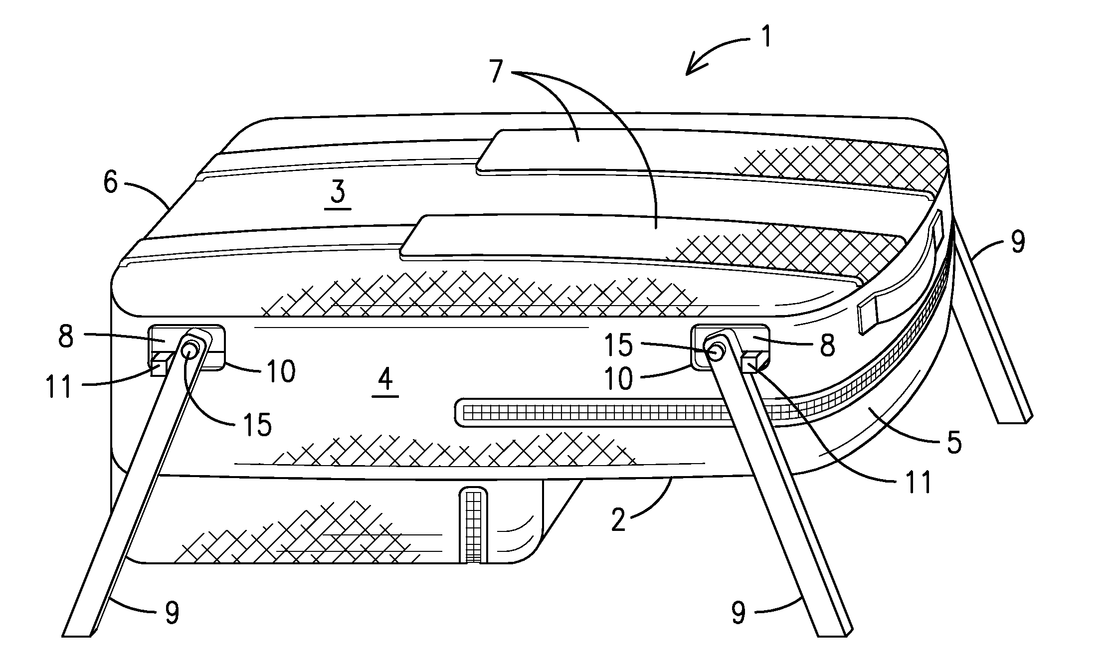
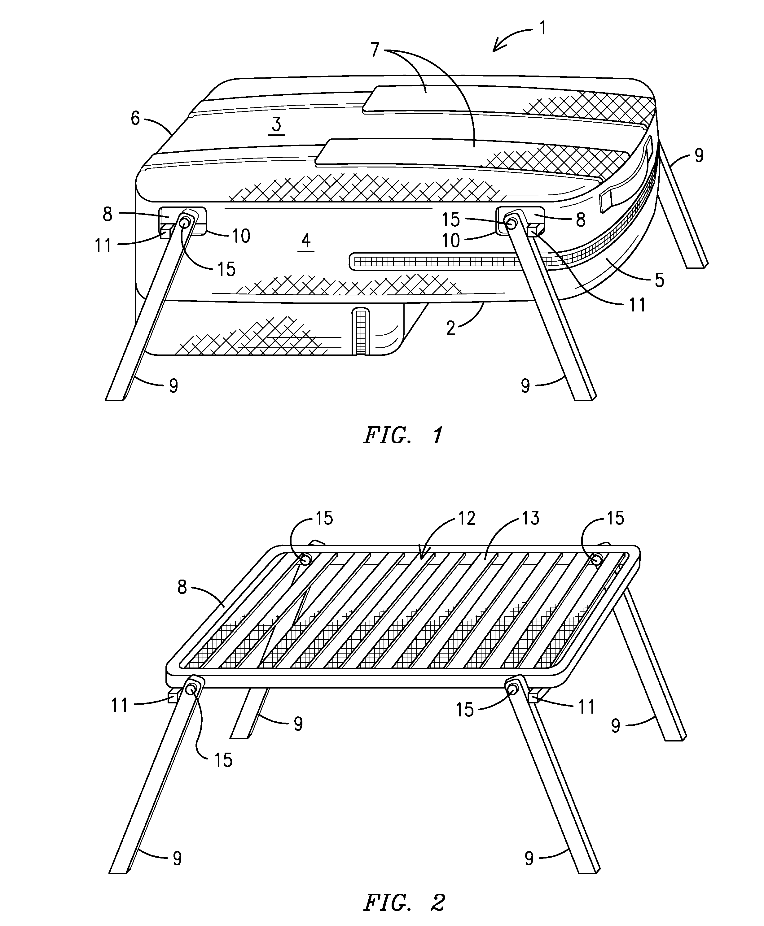
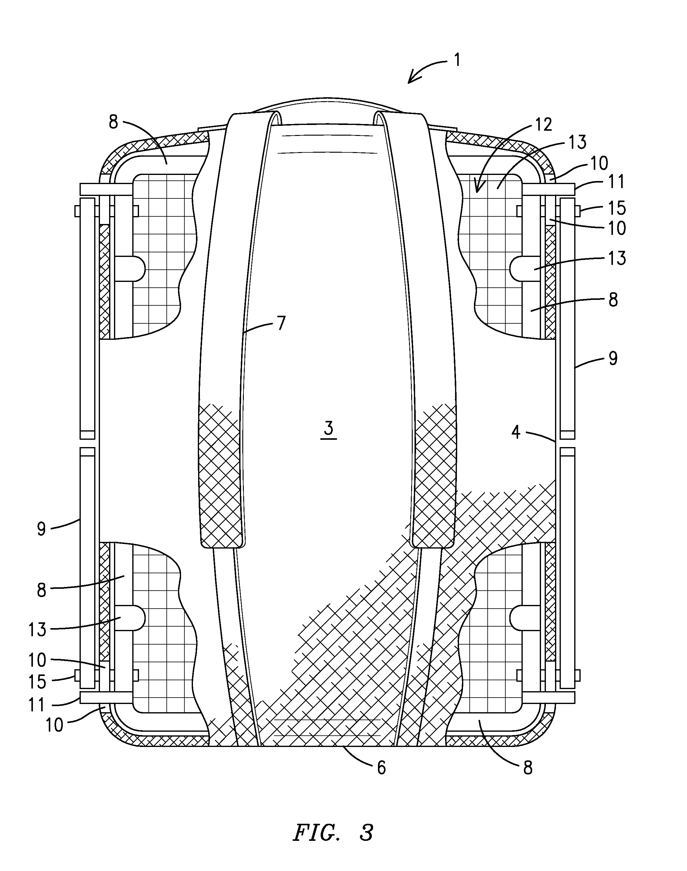
[0019]With reference to FIG. 1, a side perspective view of a backpack stool 1 of the present invention having legs in an extended position is shown. The backpack stool has a front surface 2, a rear surface 3, sides 4, a top 5 and a bottom 6. Shoulder straps 7 used for carrying the backpack stool 1 are located on the rear surface 3 of the backpack stool 1. A rigid frame 8, as shown in FIGS. 2 and 3, is located within the backpack stool 1 adjacent to the rear surface 3. The frame 8 is substantially rectangular in shape. Legs 9 are pivotally attached to the frame 8 via pivot points 15 that extend through apertures 10 located on the sides 4 of the backpack stool 1. To...


PUM


Abstract

A backpack stool (1) having a frame (8) with legs (9) attached thereto via pivot points (15) that allow a user to easily convert the backpack stool from a backpack for transporting items to a stool with a surface for sitting. To use the backpack stool as a stool, a user simple folds the legs outward from the frame into an extended position and places the ends of the legs on the ground. The user may then sit on the rear surface (3) of the backpack stool where the shoulder straps (7) are normally located. The rear surface of the backpack is preferably reinforced with a webbing (13) or other material located between the frame. To use the backpack stool as a backpack, a user simple folds the legs into a folded position so that the legs are parallel with the frame. The user may then use the shoulder straps to carry the backpack stool on the user's back.

Description

CROSS REFERENCE TO RELATED APPLICATION[0001]This application claims the benefit of U.S. Provisional Patent Application No. 61 / 212,118, filed Apr. 6, 2009. The patent application identified above is incorporated here by reference in its entirety to provide continuity of disclosure.BACKGROUND OF THE INVENTION[0002]This invention relates to backpacks, more particularly, a backpack having a frame with pivoting legs attached thereto that allows a user to easily convert the backpack into a stool with a surface for sitting.[0003]Backpacks are commonly used by students, campers, hunters and others to carry and transport items. Users of backpacks commonly find themselves outdoors where there is no place to sit except on the ground. For example, students who are waiting at a bus stop or campers or hunters who have stopped along a hike to rest are commonly left having to choose between standing or sitting on a dirty and / or wet ground. Although, there have been attempts in the past to combine c...

Claims


Application Information

Patent Timeline
IPC IPC(8): A45F4/02
CPCA45F2004/026A45F4/02
Inventor POPESCU, VIRGIL
Owner POPESCU VIRGIL
Learn More