Mass Spectrometer Using An Accelerating Traveling Wave

Active Publication Date: 2010-10-07
WISCONSIN ALUMNI RES FOUND
View PDF7 Cites 9 Cited by
  • Summary
  • Abstract
  • Description
  • Claims
  • Application Information

AI Technical Summary

Benefits of technology

[0005]The present inventors have recognized that increased velocity separation between species can be obtained through the use of a spatial- and time-variant electric field for accelerating the species. This more sophisticate

Problems solved by technology

A similar problem, albeit in the spatial dimension,

Method used


Image

  • Mass Spectrometer Using An Accelerating Traveling Wave
  • Mass Spectrometer Using An Accelerating Traveling Wave
  • Mass Spectrometer Using An Accelerating Traveling Wave

Examples


Embodiment Construction

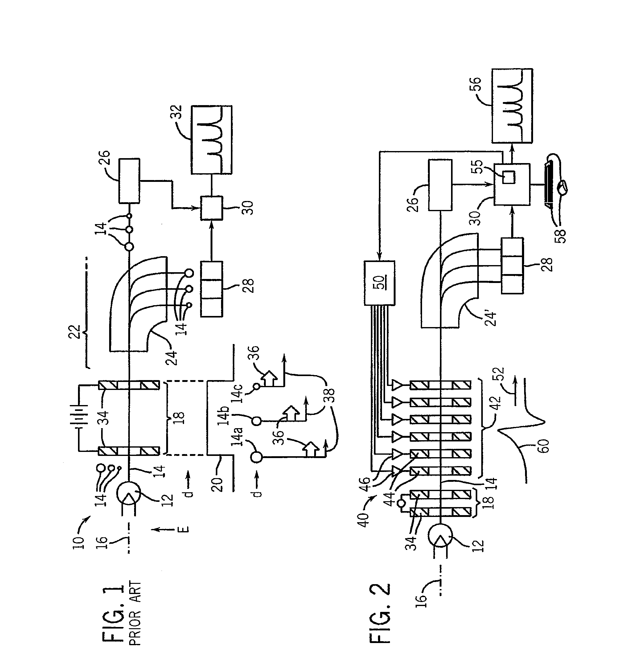
[0039]Referring now to FIG. 1, a conventional mass spectrometer 10 includes an analyte source 12 presenting a stream or pulse of charged particles 14 directed along an axis 16 into an accelerating chamber 18.

[0040]The accelerating chamber 18 typically presents a uniform and time invariant electrostatic field 20 (measured along the axis 16) that accelerates the particles 14 into a drift region 22 or a bending field 24. The former drift region 22 allows the particles 14 to separate from their velocity differences before being received by a time-of-flight detector 26 differentiating among particles by their time of arrival.

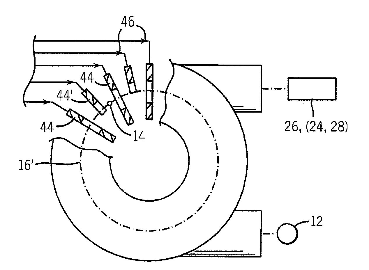
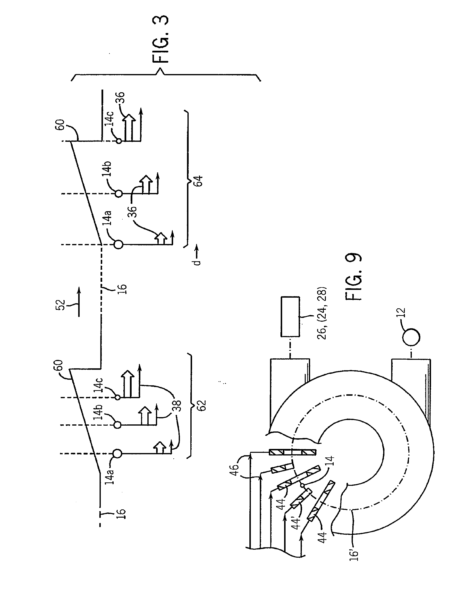
[0041]The latter bending field 24 disperses the particles 14 into a set of curved trajectories determined by the velocity differences of the particles 14 times their mass (i.e., the radius of curvature goes as mass times velocity), thus separating the particles 14 spatially along a spatial detector 28, the latter of which may distinguish among particles 14 by their s...


PUM


Abstract

A mass spectrogram employs a set of controllable electrodes to produce a time varying axially inhomogenous electric field and enhance separation of charged particles by exposing the charged particles to different electric field strengths based on their spatial positions. The fields may be tailored to provide a traveling wave that expands portions of a spectrographic plot of the particles and/or to provide focusing or other effects.

Description

CROSS-REFERENCE TO RELATED APPLICATIONSBACKGROUND OF THE INVENTION[0001]The present invention relates to mass spectrometry and, in particular, to a spectrometer providing variable and improved sensitivity.[0002]In a typical mass spectrometer, particles, such as different molecular species, are ionized and accelerated in an electric field. The acceleration of particles having the same charge will be principally dependent on the mass of the particles and thus particles may be separated by mass according to their final velocity in the electric field. Differences in velocity may be detected by a time-of-flight detector positioned after a drift region or by passing the particles through a magnetic or electric field to separate them into curving trajectories determined by mass and velocity to be received by a spatial detector.[0003]For a larger mass species, the relative difference in velocities between the particles becomes much smaller. For example, in biological molecules with a mass a...

Claims


Application Information

Patent Timeline
IPC IPC(8): B01D59/44H01J49/40
CPCH01J49/403
Inventor MACKIE, THOMAS R.HECHT, ADAM A.BISOGNANO, JOSEPH J.
Owner WISCONSIN ALUMNI RES FOUND
Why Eureka
Try Eureka