Early quench detection in a superconducting article

a superconducting and early quench detection technology, applied in the direction of superconductor devices, normal-superconductive switchable devices, emergency protective arrangements for limiting excess voltage/current, etc., can solve the problem of slow thermal instability development, detection and management of superconducting devices, and inhibiting its propagation along the hts conductor

Active Publication Date: 2010-10-07
SUPERPOWER INC A SUBSIDIARY OF ROYAL PHILIPS ELECTRONICS
View PDF8 Cites 16 Cited by
  • Summary
  • Abstract
  • Description
  • Claims
  • Application Information

AI Technical Summary

Benefits of technology

[0022]FIG. 8 is a graph of magnetic field induction at the gap between superconductive segments measured simultaneously with voltage drop across the superconductive segments, and illustrating that the effect of selective heating of the superconductive segment is readily detected, even at current levels well below the critical quench current of the segment, in accordance with an aspect of the present invention;

Problems solved by technology

However, it was not until somewhat recently that oxide-based high-temperature (high-Tc) superconductors have been discovered.
At the same time, whenever quench in HTS conductors occurs, its detection and management presents a serious engineering problem.
The same factors that suppress quench occurrence result in very slow development of thermal instability and inhibiting of its propagation along the HTS conductor.
Slow developing thermal instability means that initially a small local hot-spot (or quench region) is formed in the wire, and significant heating can occur there prior to the surrounding region quenching to the normal resistive state of the conductor.
This leads to a quick local degradation of the YBCO material due to oxygen loss or due to complete conductor burn-out.
At the same time, voltage associated with formation of one or more localized hot-spots is always small, proportional to the hot-spot dimensions, which makes it hard to detect the quench signal in the background of voltage noise.

Method used


Image

  • Early quench detection in a superconducting article
  • Early quench detection in a superconducting article
  • Early quench detection in a superconducting article

Examples


Embodiment Construction

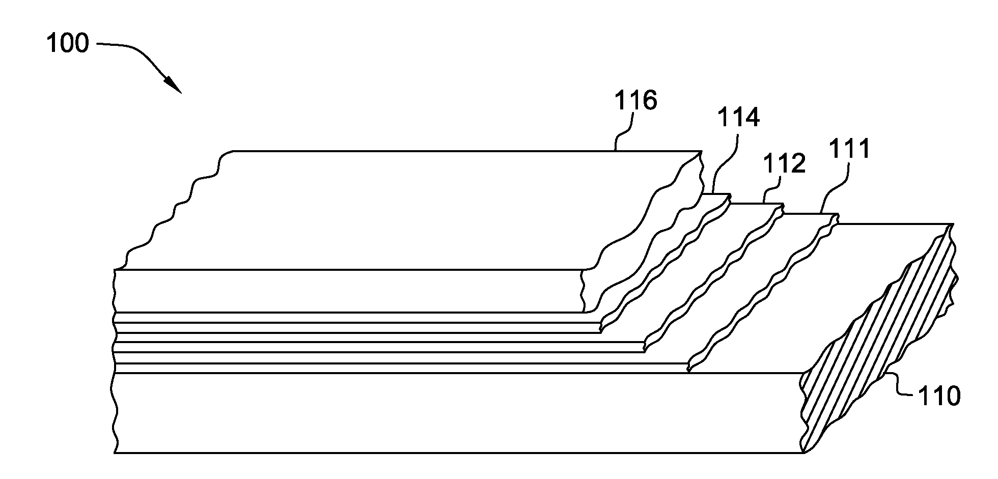
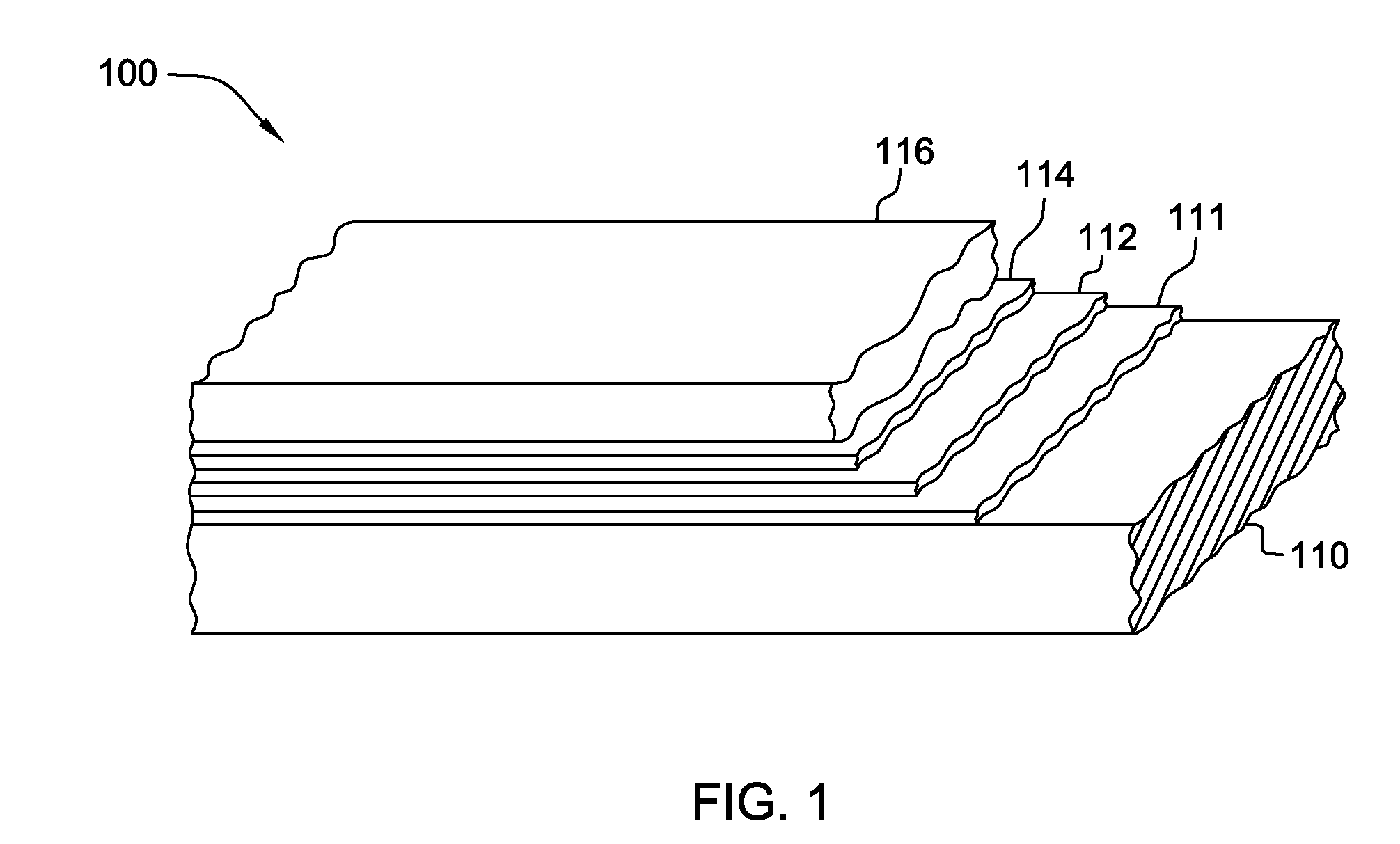
[0031]Referring to FIG. 1, the general layered structure of an HTS conductor 100 is depicted which can be employed in a superconducting article, in accordance with the present invention. The HTS conductor 100 includes a substrate 110, a buffer layer 111 overlying substrate 110, an HTS layer 112, followed by a capping layer 114, (typically a noble metal layer) and a stabilizer layer 116 (typically a non-noble metal). In the embodiment depicted in FIG. 1, buffer layer 111, HTS layer 112, capping layer 114 and stabilizer layer 116 are collectively referred to as the superconducting region, which as illustrated, is disposed along one main surface of substrate 110. Note that in a fault current limiter application of a superconducting article such as described herein, stabilizer layer 116 would be omitted, with the superconducting region comprising buffer layer 111, HTS layer 112, and capping layer 114.

[0032]The substrate 110 is typically in a tape-like configuration, having a high aspect...


PUM

PropertyMeasurementUnit
lengthaaaaaaaaaa
lengthaaaaaaaaaa
lengthaaaaaaaaaa

Abstract

A superconducting article is provided which incorporates an early quench detection facility. The superconducting article includes a first superconductive segment and a second superconductive segment, along with a magnetic field sensor(s). The magnetic field sensor(s) is disposed to monitor relative change in strength of a net magnetic field generated by a first current passing through the first superconductive segment and a second current passing through the second superconductive segment. A relative change in strength of the net magnetic field indicates degradation of a critical quench current of the first superconductive segment or the second superconductive segment, caused for example, by formation of one or more hot-spots or quench regions in the first or second superconductive segment. The indication of degradation is thus obtained prior to complete superconductive segment quenching.

Description

TECHNICAL FIELD [0001]The present invention relates in general to superconducting articles, and in particular, to superconducting articles and methods of fabrication thereof with quench detection. More particularly, the present invention relates to superconducting articles comprising a high-temperature superconductor (HTS) with a detection facility for early detection of degradation of a superconducting characteristic(s) of the HTS conductor.BACKGROUND OF THE INVENTION [0002]Superconductor materials have long been known and understood by the technical community. Low-temperature (low-Tc) superconductors exhibiting superconductive properties at temperatures requiring use of liquid helium (4.2° K.), have been known since about 1911. However, it was not until somewhat recently that oxide-based high-temperature (high-Tc) superconductors have been discovered. Around 1986, a first high-temperature superconductor (HTS), having superconductive properties at a temperature above that of liquid...

Claims


Application Information

Patent Timeline
Patent Type & Authority Applications(United States)
IPC IPC(8): H02H7/00H01L39/24
CPCH01L39/16Y10T29/49014Y02E40/68H02H7/001Y02E40/60H10N60/30
Inventor MARTCHEVSKII, MAXIM
Owner SUPERPOWER INC A SUBSIDIARY OF ROYAL PHILIPS ELECTRONICS
Why Eureka
Try Eureka