Light emitting tufted carpet

a technology of tufted carpet and light-emitting materials, which is applied in the direction of lighting support devices, coupling device connections, lighting and heating apparatus, etc., can solve the problems of heat generated by leds, traffic walking over the carpet, and other (pressure) influences, and achieve the effect of providing strength to the carpet, low cost and easy manufacturing of a light-permeable structur

Inactive Publication Date: 2010-10-07
SIGNIFY HLDG BV
View PDF14 Cites 10 Cited by
  • Summary
  • Abstract
  • Description
  • Claims
  • Application Information

AI Technical Summary

Benefits of technology

[0053]These ‘secondary backing layers’ have an advantage in that they are well-suited for carpet backing and fit in well with the carpet manufacturing method used in carpet factories. Advantages of using the secondary backing layer may be protection of the LEDs, optional power sources, and conductors) as well as providing strength to the carpet. Hence, preferably the tufted carpet according to the invention comprises the secondary backing layer. The invention is however not restricted to the presence of the secondary backing layer, but further and/or other layers may be present, such as on the side of the secondary backing layer facing away from the adhesive layer (i.e. between the secondary backing layer bottom face and the carpet bottom face), but also elsewhere (see also above).
[0054]At least one of the primary backing layer and th

Problems solved by technology

A disadvantage of prior art may be that when embedding LEDs in carpet the protection of the LEDs and/or other electronic components against wear from traffic walking over the carpet, or other (pressure) influences, may be difficult.
Further,

Method used


Image

  • Light emitting tufted carpet
  • Light emitting tufted carpet
  • Light emitting tufted carpet

Examples


Embodiment Construction

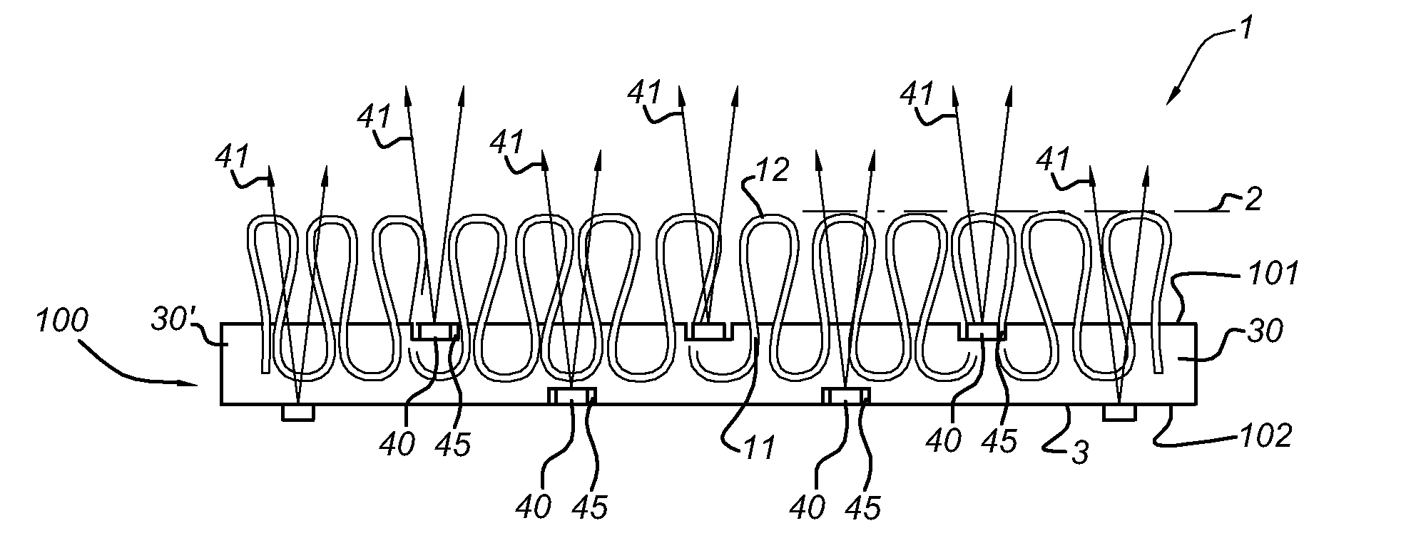
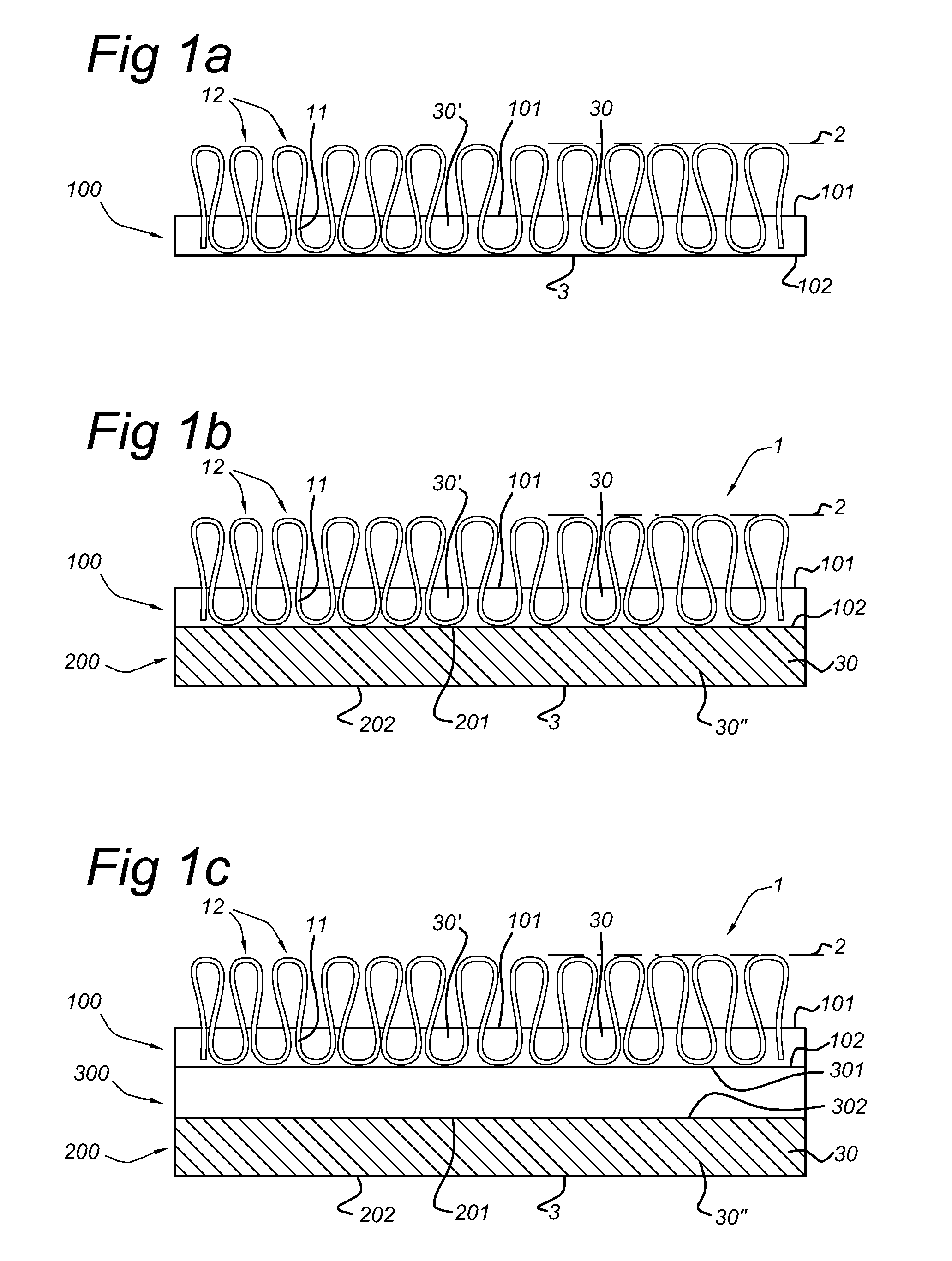
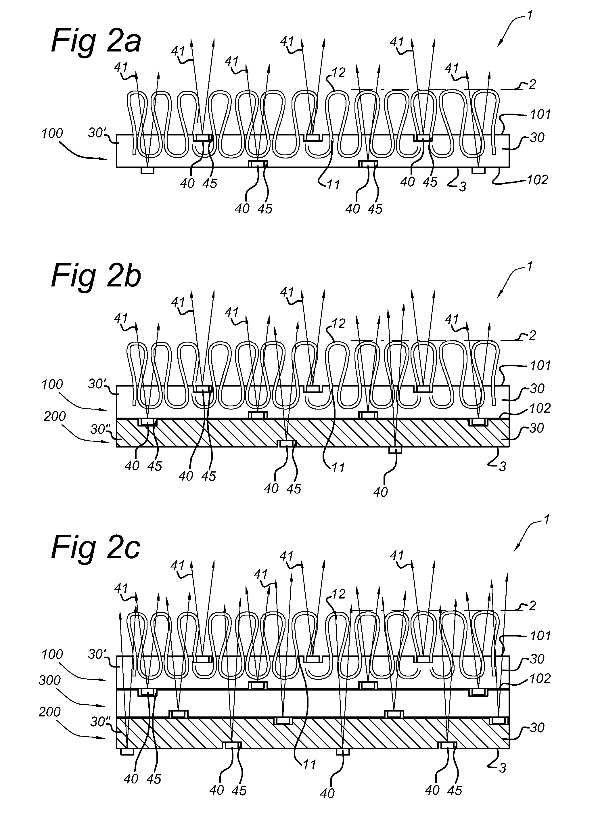
[0090]FIGS. 1a-1c schematically depict embodiments of a carpet 1 comprising a primary backing layer 100 (FIG. 1a), a primary backing layer 100 and a secondary backing layer 200 (FIG. 1b), and a primary backing layer 100, an adhesive layer 300 and a secondary backing layer 200, respectively, wherein in the latter the adhesive layer 300 is arranged between the primary backing layer 100 and the secondary backing layer 200. The adhesive layer 300 may also comprise domains (not depicted); i.e. the adhesive layer 300 may be arranged between part(s) of the primary backing layer 100 and the secondary backing layer 200.

[0091]The primary backing layer 100 has a primary backing layer top face 101 and a primary backing bottom face 102. The secondary backing layer 200 has a secondary backing layer top face 201 and a secondary backing bottom face 202. The adhesive layer 300 has an adhesive layer top face 301 and an adhesive layer bottom face 301. The carpet has a carpet top face 2, i.e. the carpe...


PUM


Abstract

The invention provides a light emitting tufted carpet (1). The carpet (1) comprises a primary backing layer (100), an optional secondary backing layer (200), an optional adhesive layer (300), a plurality of carpet integrated LEDs (40) arranged to generate carpet light (41), and a first electric conductor (10) and a second electric conductor (20). The first electric conductor (10) and the second electric conductor (20) are arranged to provide power from a power source (50) to the LEDs (40). The primary backing layer (100) comprises a first felt layer (30′), or the optional secondary backing layer (200) comprises second felt layer (30″), or both the primary backing layer (100) and the optional secondary backing layer (200) comprise felt layers (30′,30″). One or more of the first electric conductor (10) and the second electric conductor (20) are at least partially integrated in one or more of the first felt layer (30′) and the second felt layer (30″).

Description

FIELD OF THE INVENTION[0001]The present invention relates to textile materials having also a light emitting function. The invention especially relates to a carpet comprising a primary backing layer, yarns forming tufts on a carpet side of the primary backing layer, a secondary backing layer, and an adhesive layer arranged between the primary and secondary backing layers.BACKGROUND OF THE INVENTION[0002]Carpets generally comprise a primary backing layer provided with yarns forming tufts (on its side facing the user during its use as carpet), a secondary backing layer, and in general an adhesive layer provided between the primary backing layer and the secondary backing layer. The yarns penetrate the primary backing layer to form tufts projecting from the pile surface on which people can walk, etc. The yarns are normally loose and need to be adhered with adhesive (from an adhesive layer). The adhesive layer which may be present on the backside of the primary backing adheres the tufts t...

Claims


Application Information

Patent Timeline
IPC IPC(8): F21S4/00
CPCD05C17/02F21V33/006B32B37/14A47G2200/08B60N3/042B60N3/048A47G27/0243F21S8/032
Inventor VAN HERPEN, MAARTEN MARINUS JOHANNES WILHELMUS
Owner SIGNIFY HLDG BV
Why Eureka
Try Eureka