

Virtual channel enabling device for use in endoscopic instrument insertion and body cavity cleansing
a technology of endoscopy instruments and enabling devices, which is applied in the field of virtual channel enabling devices for use in endoscopic instruments insertion and body cavity cleansing, can solve the problems of increasing the cross sectional profile of the endoscope to a problematic degree, fecal debris is left in place, and the simultaneous use of the endoscope is not permitted, so as to facilitate surgical procedures, enhance the insertion and control of the device within the body cavity, and facilitate the effect of operative procedures
- Summary
- Abstract
- Description
- Claims
- Application Information
AI Technical Summary
Benefits of technology
Problems solved by technology
Method used
Image

Examples
example
Typical Device of the Present Invention
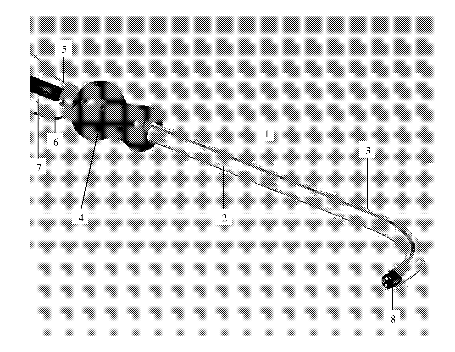
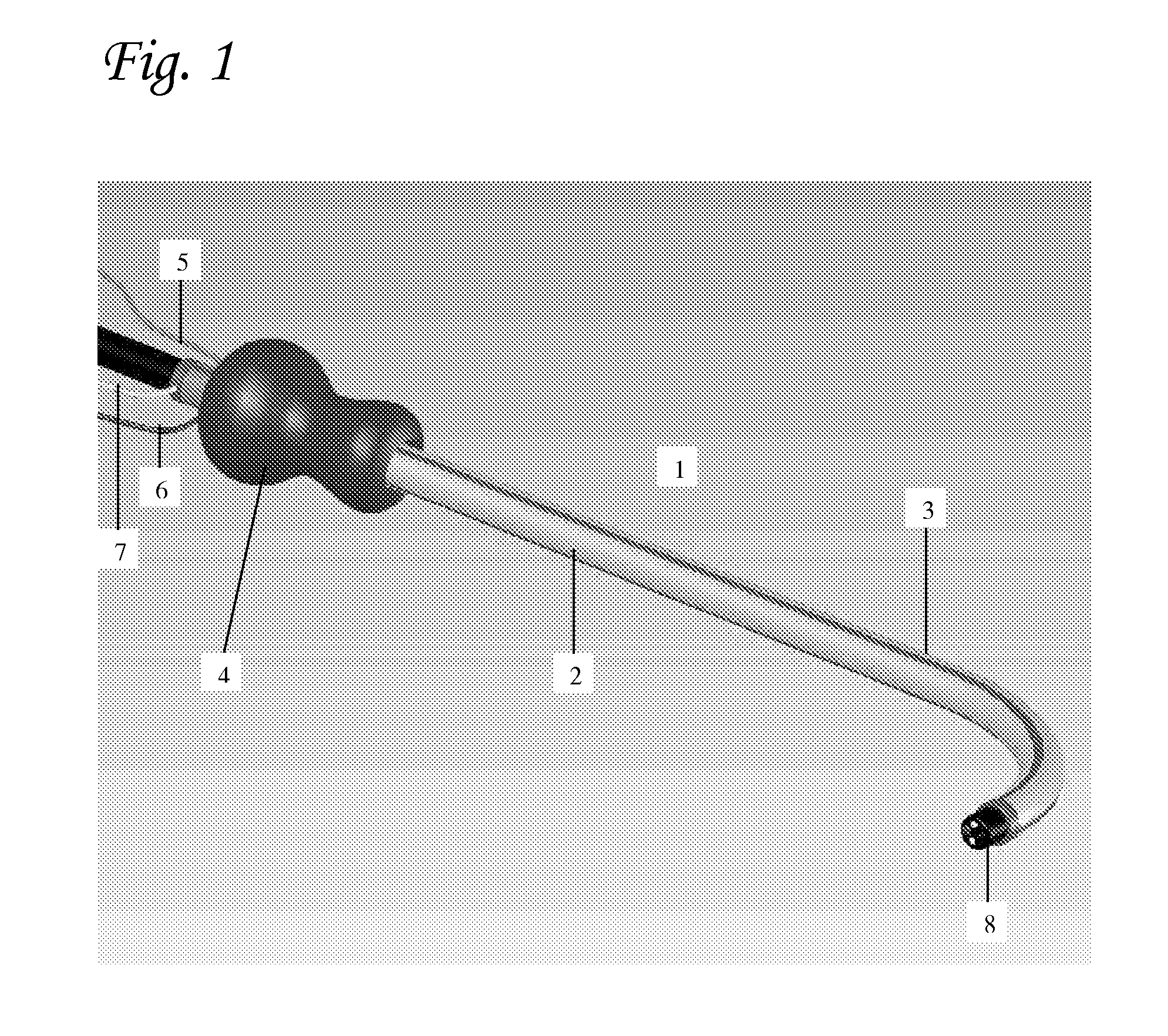
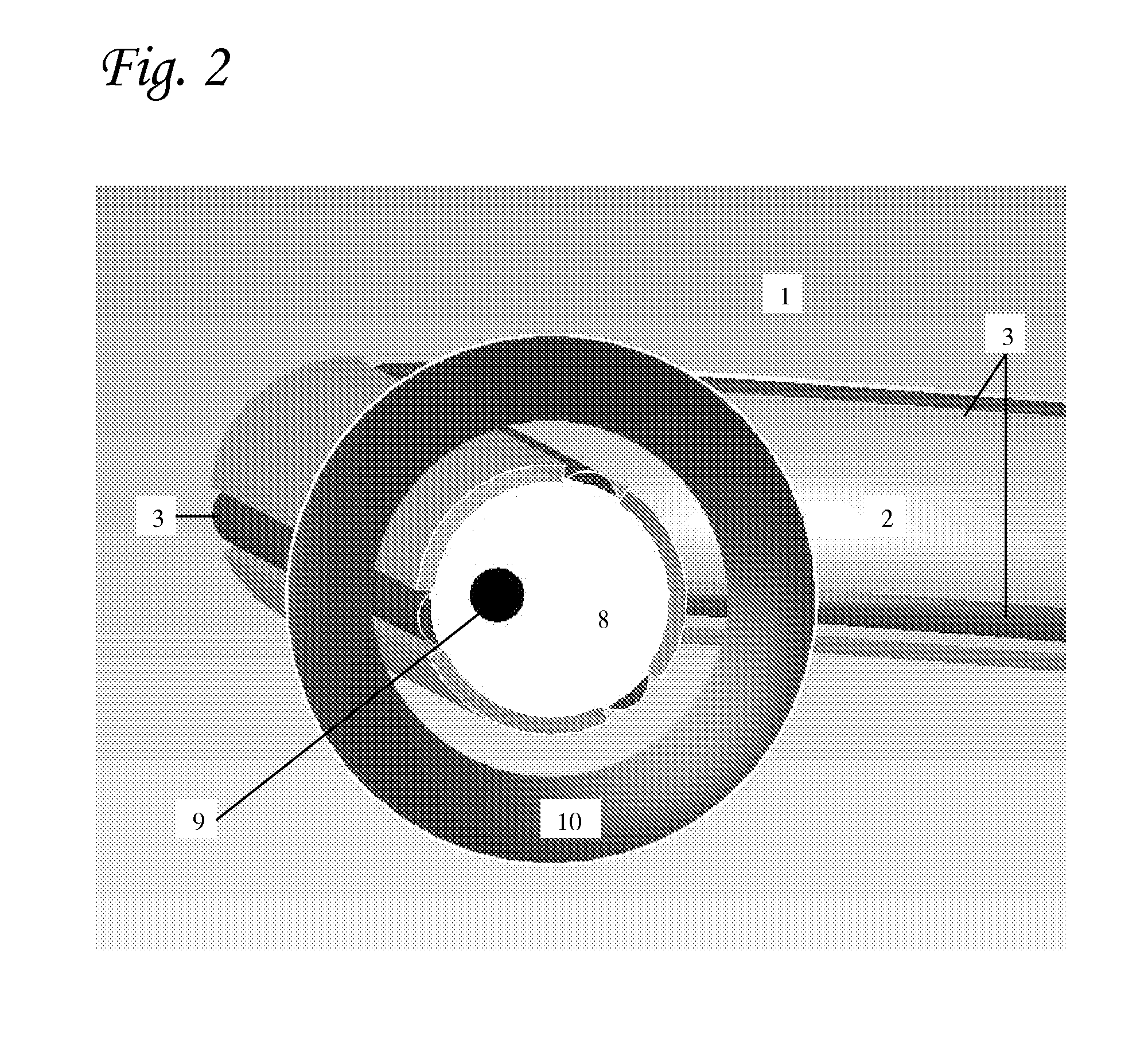
[0167]FIG. 11A is a three dimensional solid view of a typical preferred embodiment of the device of the present invention, comprising two longitudinal balloons, each having a diameter of 6 mm in their inflated state. When the balloons are inflated, three longitudinal lumens (“virtual lumens”; one large, two small) are created between the thin compliant internal sleeve upon which the balloons are mounted and the outer membrane of the device, which is brought into contact with the colonic wall by pressure from said inflated balloons. The various components of this device are shown in more detail in FIG. 11B, wherein the two inflatable balloons 32, are shown mounted on a compliant inner sleeve 37 and covered by external membrane 38. As illustrated, said inner sleeve 37 fits snugly over the colonoscope 38.
[0168]In this example, upon inflation of the balloons (inflatable channels) 32, three longitudinally-disposed virtual lumens are created: a large...
PUM
 Abstract
Description
Claims
Application Information