Implant, method and device for producing an implant of this type

a technology of implanted stents and implants, which is applied in the field of implanted stents, can solve the problems of promoting undesirable formation of thrombosis, reducing the treatment effect, and narrowing of the vessel section (restenosis) following a stent implant, and achieves the effects of low cost, convenient production and suitable treatmen

Inactive Publication Date: 2010-10-07
ACANDIS
View PDF6 Cites 25 Cited by
  • Summary
  • Abstract
  • Description
  • Claims
  • Application Information

AI Technical Summary

Benefits of technology

[0013]A further advantage of the present invention is that the implant is particularly suitable for treatment of aneurysms. The narrow mesh width of aneurysm stents required for covering the aneurysm leads to adverse side effects, such as restenosis, and to the formation of thrombi. These undesirable side effects are avoided or at least occur to a lesser extent by the non-continuous profiling of the wall element.
[0014]The present invention is not limited to stents, in particular intraluminal stents, but includes implants generally, in particular medical or endovascular implants with an incident flow of fluid, or which generally have a flow conduction function, such as stent grafts, protection filters, etc.
[0015]In a preferred embodiment of the present invention, the wall element has profile elements with incident flow surfaces arranged non-continuously. The incident flow surfaces are not connected continuously to one another, but have generally abrupt transitions, so that overall a non-continuous profile or a non-continuous contouring of the inside of the wall element results. A wall element of this type or an implant with a wall element of this type can be produced easily and with comparatively low costs.
[0016]A particularly effective influencing of the flow behaviour is achieved if the incident flow surfaces have a main orientation which essentially extends in the direction of flow.
[0017]The incident flow surfaces can in each case be arranged, with respect to the wall element, with a tilt and / or a convex curve and / or a concave curve. By the different formation of the incident flow surfaces, a different influencing of the flow behaviour can be established.
[0018]In a preferred embodiment of the present invention, the non-continuous profiling of the wall element is achieved by the incident flow surfaces each having an end at a distance from the wall element, in particular a free end, which when implanted projects into the fluid flow. The profile elements here can form a wall element profile which is sawtooth-like in cross-section. A profile cross-section of this type can be produced in a simple manner.

Problems solved by technology

The narrowing of vessel sections (restenosis) following a stent implant continues to be a major clinical problem in spite of numerous further developments in this field.
Moreover, it is known that stented vessel sections not only lead to a change in the shear stress at the vessel wall, but also can promote the undesirable formation of thrombi due to changes in the haemodynamics of the natural blood flow.
Needless to say, fixing of the flow cylinder in the stent presents production problems.
In addition, the flow cylinder impairs the flexibility of the stent.
There are also production problems with this stent.

Method used


Image

  • Implant, method and device for producing an implant of this type
  • Implant, method and device for producing an implant of this type
  • Implant, method and device for producing an implant of this type

Examples


Embodiment Construction

[0030]Certain terminology is used in the following description for convenience only and is not limiting. The words “inner,”“outer,”“inwardly” and “outwardly” refer to directions toward and away from, respectively, the geometric center of the implant or device and designated parts thereof. Additionally, the terms “a,”“an” and “the,” as used in the specification, mean “at least one.” The terminology includes the words above specifically mentioned, derivatives thereof, and words of similar import.

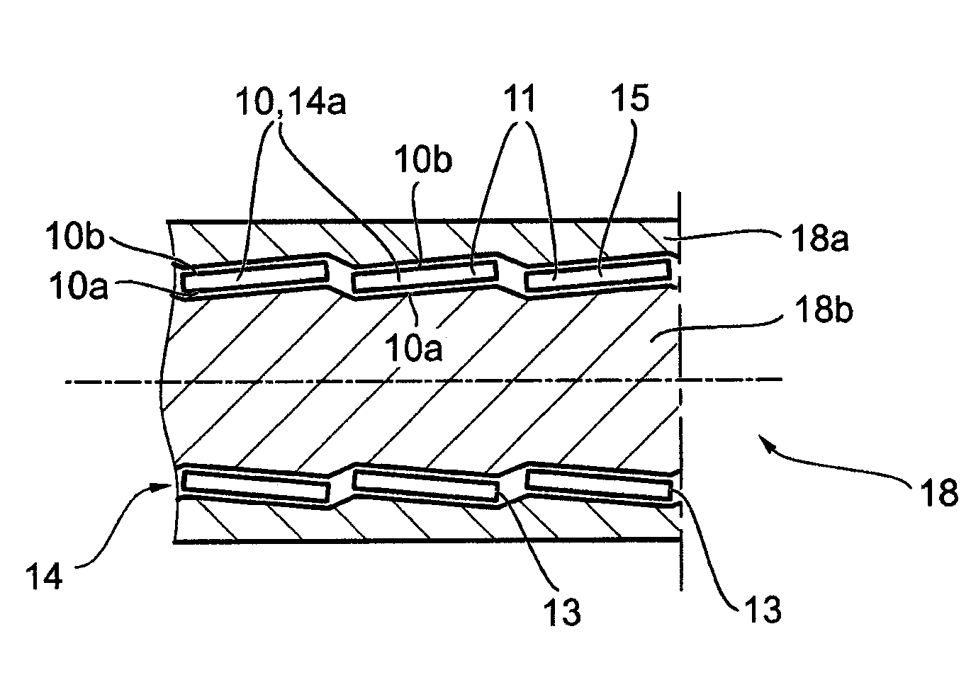
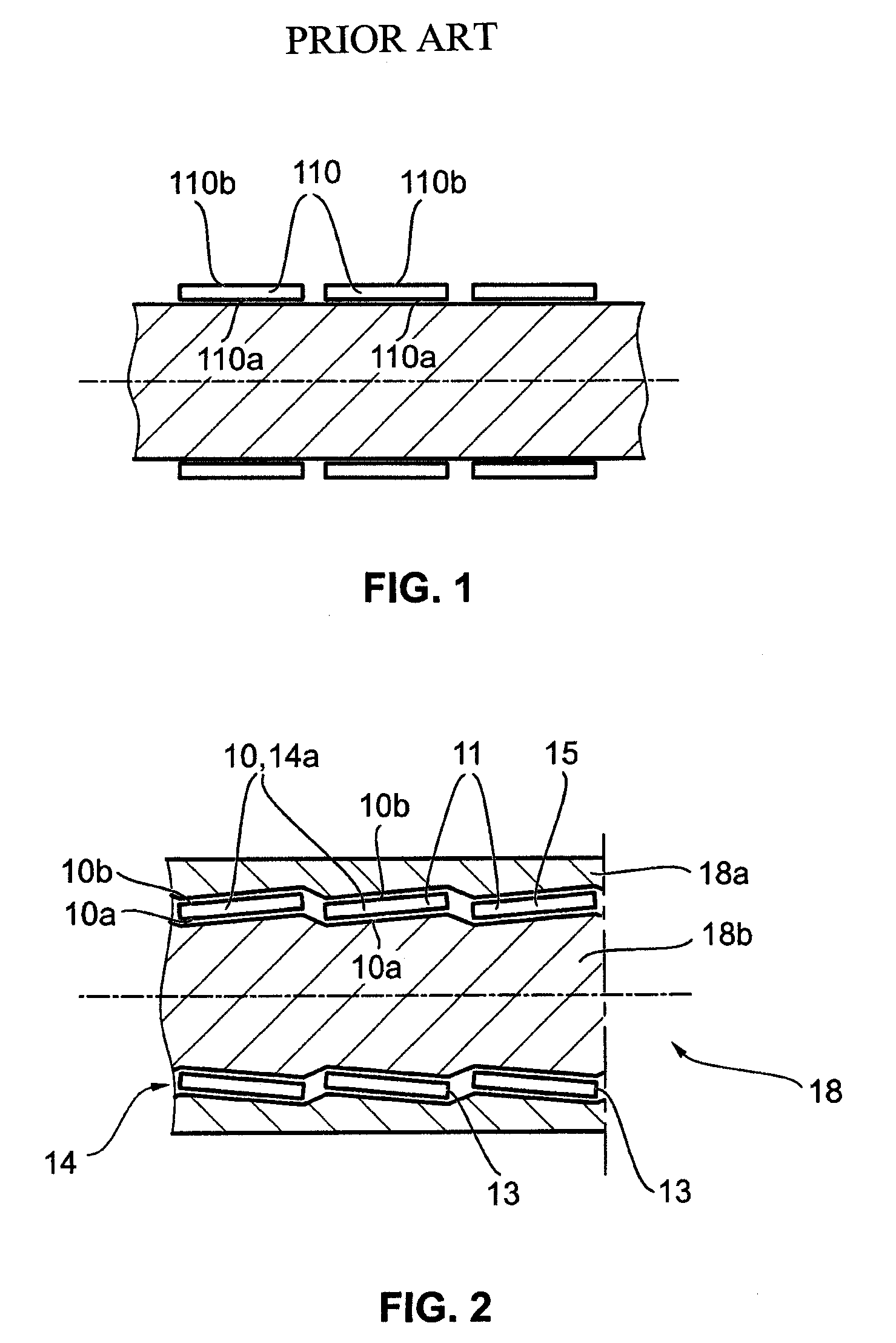
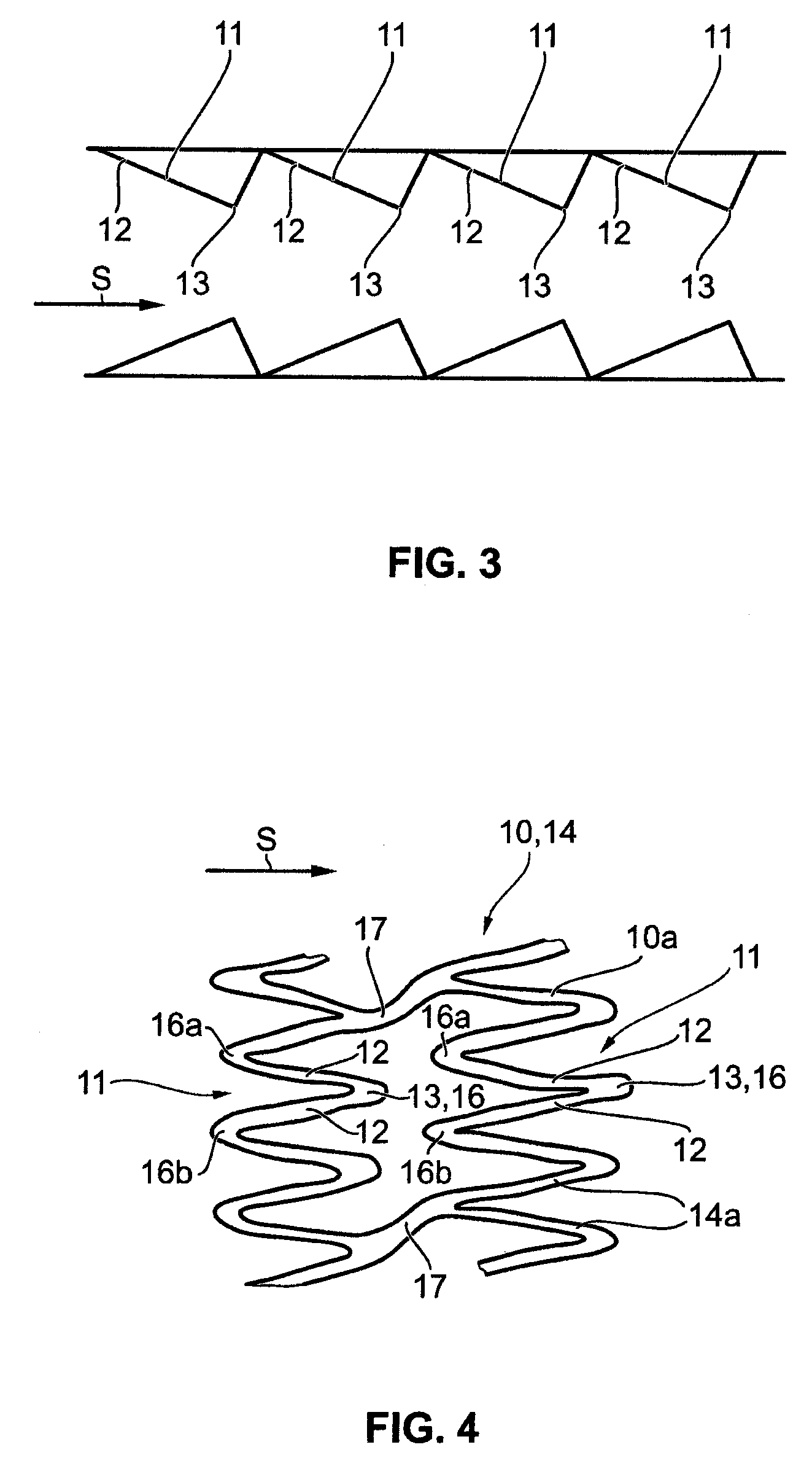
[0031]Referring to the drawings in detail, wherein like numerals indicate like elements throughout, there is shown in FIGS. 2-4 preferred embodiments of an implant. In contrast to the conventional implant shown in FIG. 1, the design elements or grid elements 14a of the implant according to a preferred embodiment of the present invention (FIG. 2) are arranged in a different plane to an inner surface 10a of non-profiled wall sections, and in particular such that a wall element 10 has a non-conti...


PUM


Abstract

An implant includes a wall element (10) which, when implanted, comes into contact with a fluid, the wall element (10) being adapted to influence the flow behaviour of the fluid. The wall element (10) has a non-continuous profile.

Description

CROSS-REFERENCE TO RELATED APPLICATIONS[0001]This application is a Section 371 of International Application No. PCT / EP2008 / 002509, filed Mar. 28, 2008, which was published in the German language on Oct. 9, 2008, under International Publication No. WO 2008 / 119520 A1 and the disclosure of which is incorporated herein by reference.BACKGROUND OF THE INVENTION[0002]The present invention relates to an implant, a method and a device for producing an implant of this type.[0003]An implant, such as that described in EP 1 153 581 A1, is known. The narrowing of vessel sections (restenosis) following a stent implant continues to be a major clinical problem in spite of numerous further developments in this field. In this context, it is generally acknowledged that neointimal hyperplasia is the chief cause of restenosing following a stent implant. Although the mechanisms responsible for the occurrence of restenosis have not yet been fully clarified, the damage to the endothelium and the smooth musc...

Claims


Application Information

Patent Timeline
Patent Type & Authority Applications(United States)
IPC IPC(8): A61F2/82A61F2/06A61F2/91A61F2/915
CPCA61F2/91A61F2/915A61F2210/0076A61F2002/91558A61F2002/068
Inventor SCHUESSLER, KIRSI
Owner ACANDIS
Why Eureka
Try Eureka