Method and system for actively tuning a valve

a technology of active tuning and valve, which is applied in the direction of machines/engines, instruments, analogue processes for specific applications, etc., can solve the problems of adding to the maintenance and calibration requirements of the turbomachine, and the cost of providing three manifold devices for each combustion manifold

Inactive Publication Date: 2010-10-07
GENERAL ELECTRIC CO
View PDF13 Cites 10 Cited by
  • Summary
  • Abstract
  • Description
  • Claims
  • Application Information

AI Technical Summary

Problems solved by technology

Providing three manifold devices for each combustion manifold is expensive,

Method used


Image

  • Method and system for actively tuning a valve
  • Method and system for actively tuning a valve
  • Method and system for actively tuning a valve

Examples


Embodiment Construction

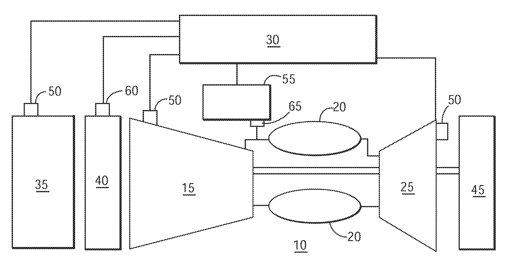
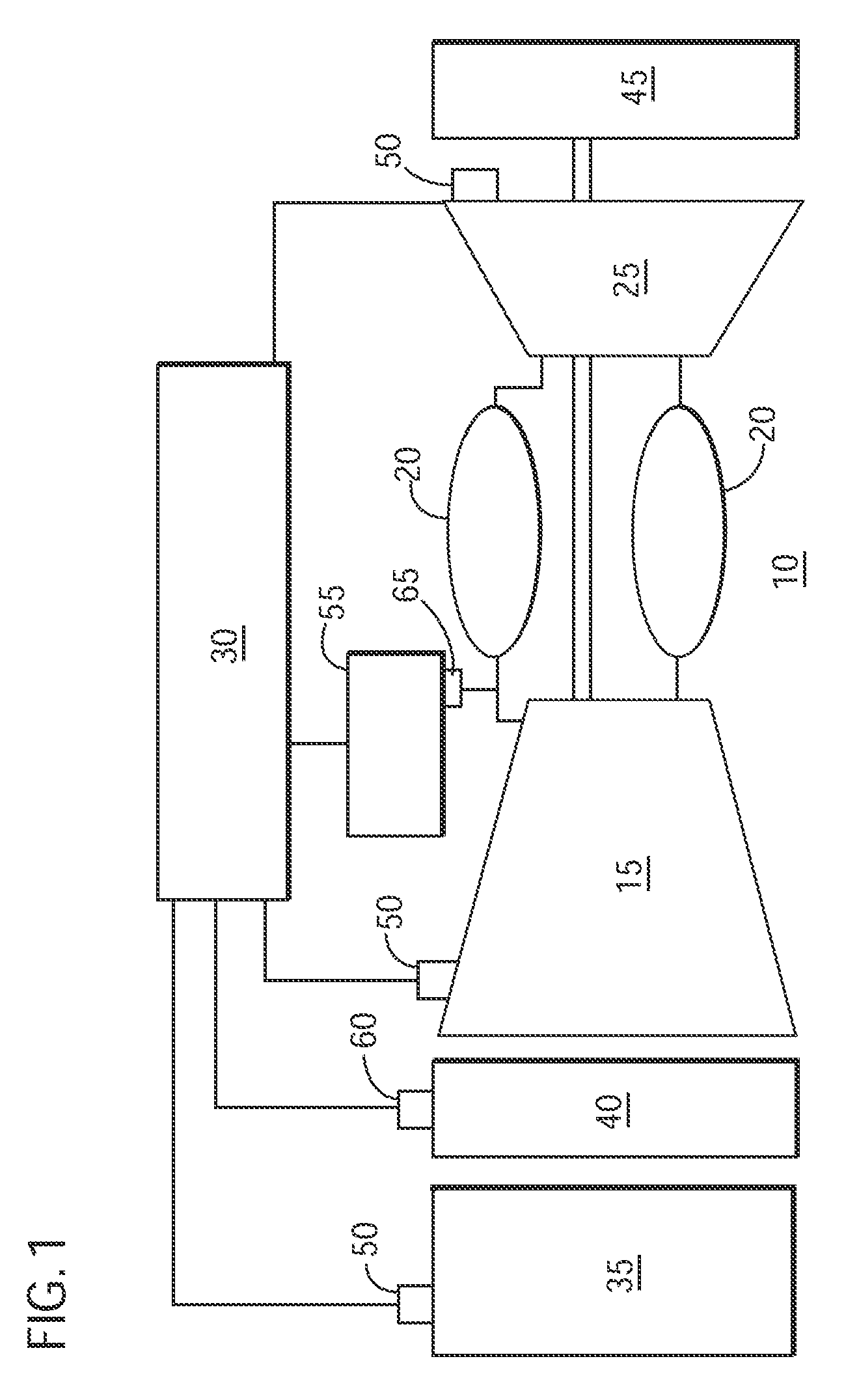
[0012]Certain terminology is used herein for convenience only and is not to be taken as a Limitation on the invention. For example, words such as “upper,”“lower,”“left, ”“front”, “right,”“horizontal,”“vertical,”“upstream,”“downstream,”“fore”, and “aft” merely describe the configuration shown in the Figures. Indeed, the components may be oriented in any direction and the terminology, therefore, should be understood as encompassing such variations unless specified otherwise. As used herein, “parameters” and similar terms refer to items that can be used to define the operating conditions of a turbomachine, such as temperatures, pressures, and flows at defined locations in the turbomachine that can be used to represent an operating condition.

[0013]The following discussion focuses on an embodiment of the present invention integrated with a turbomachine, such as, but not limiting of, a gas turbine. Other embodiments of the present invention may be integrated with other systems that compri...


PUM


Abstract

An embodiment of the present invention has the technical effect of utilizing a model-based system and real time data to adjust a parameter of at least one valve. An embodiment of the present invention may reduce the need of multiple sensors within a fuel system by integrating a model-based controller with real-time or approximately real-time data to adjust a parameter of at least one valve. An embodiment of the present invention may utilize a model-based controller to calculate the fuel flow through the at least one valve, in or near real-time.

Description

BACKGROUND OF THE INVENTION[0001]The present invention relates generally to a control system for a turbomachine valve; and more particularly to a system for actively adjusting a position of the turbomachine valve.[0002]Turbomachines, such as, but not limiting of gas turbines generally have control systems (“controllers”) for monitoring and controlling purposes. These controllers govern a position, such as a valve opening that are used, for example, but not limiting of, in the combustion system of the gas turbine. To minimize the levels of the generated emissions, some combustion systems may include control-scheduling algorithms that receive data on the firing of the turbomachine, and an operation mode of the combustion system. These algorithms may then generate a required valve position.[0003]Generally, the algorithm(s) incorporate a scheduled fuel split and a calibration curve to determine the amount of fuel that flows to a fuel nozzle in a combustor. The algorithm relates the desi...

Claims


Application Information

Patent Timeline
IPC IPC(8): F02C9/00
CPCF02C9/263F02C7/232
Inventor TONG, ERNEST H.HEALY, TIMOTHY A.FREDERICK, GARTH C.
Owner GENERAL ELECTRIC CO
Why Eureka
Try Eureka