
Downhole sensor systems and methods thereof

Active Publication Date: 2010-10-14
SCHLUMBERGER TECH CORP
View PDF17 Cites 29 Cited by
  • Summary
  • Abstract
  • Description
  • Claims
  • Application Information

AI Technical Summary

Benefits of technology

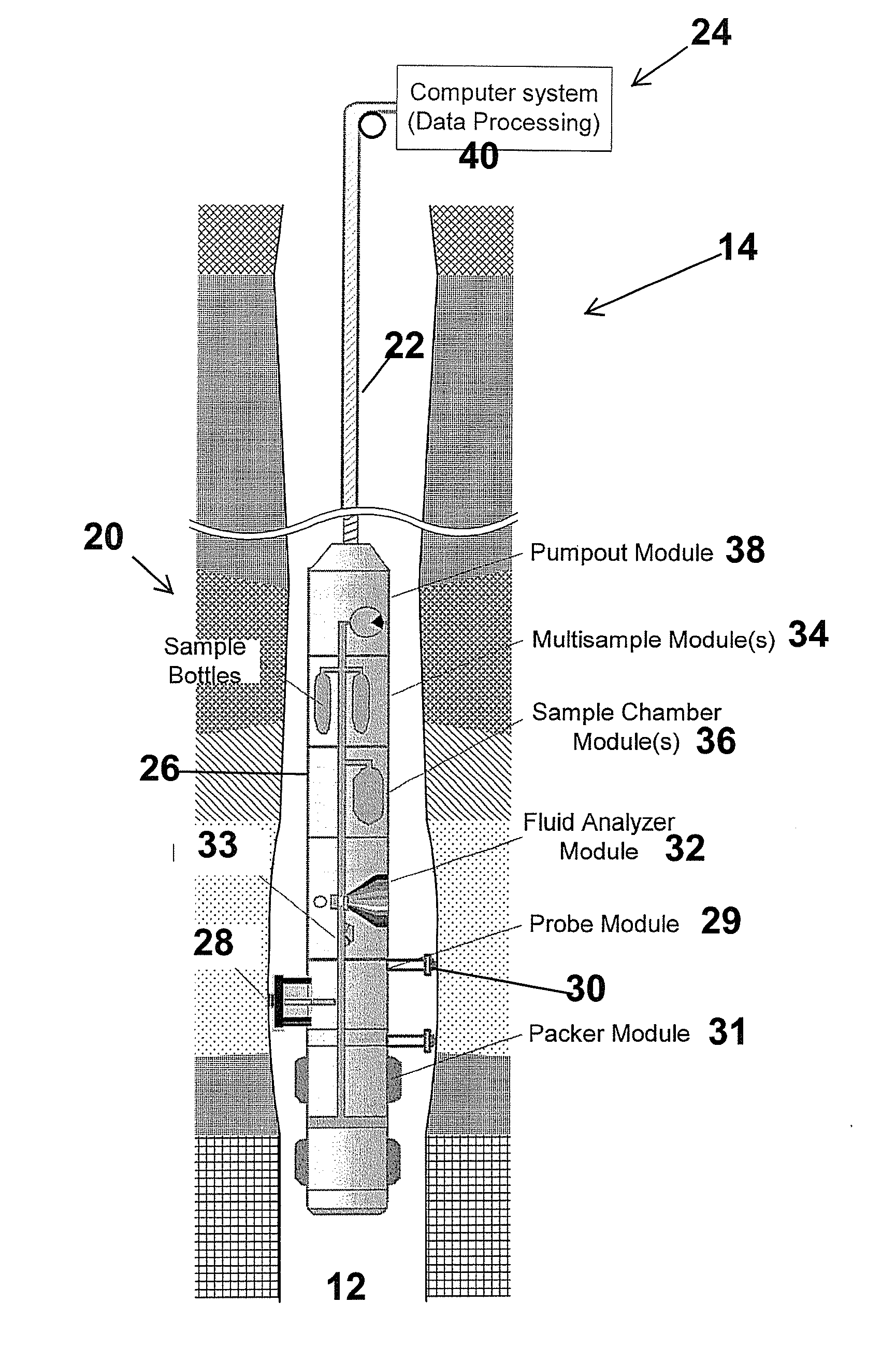
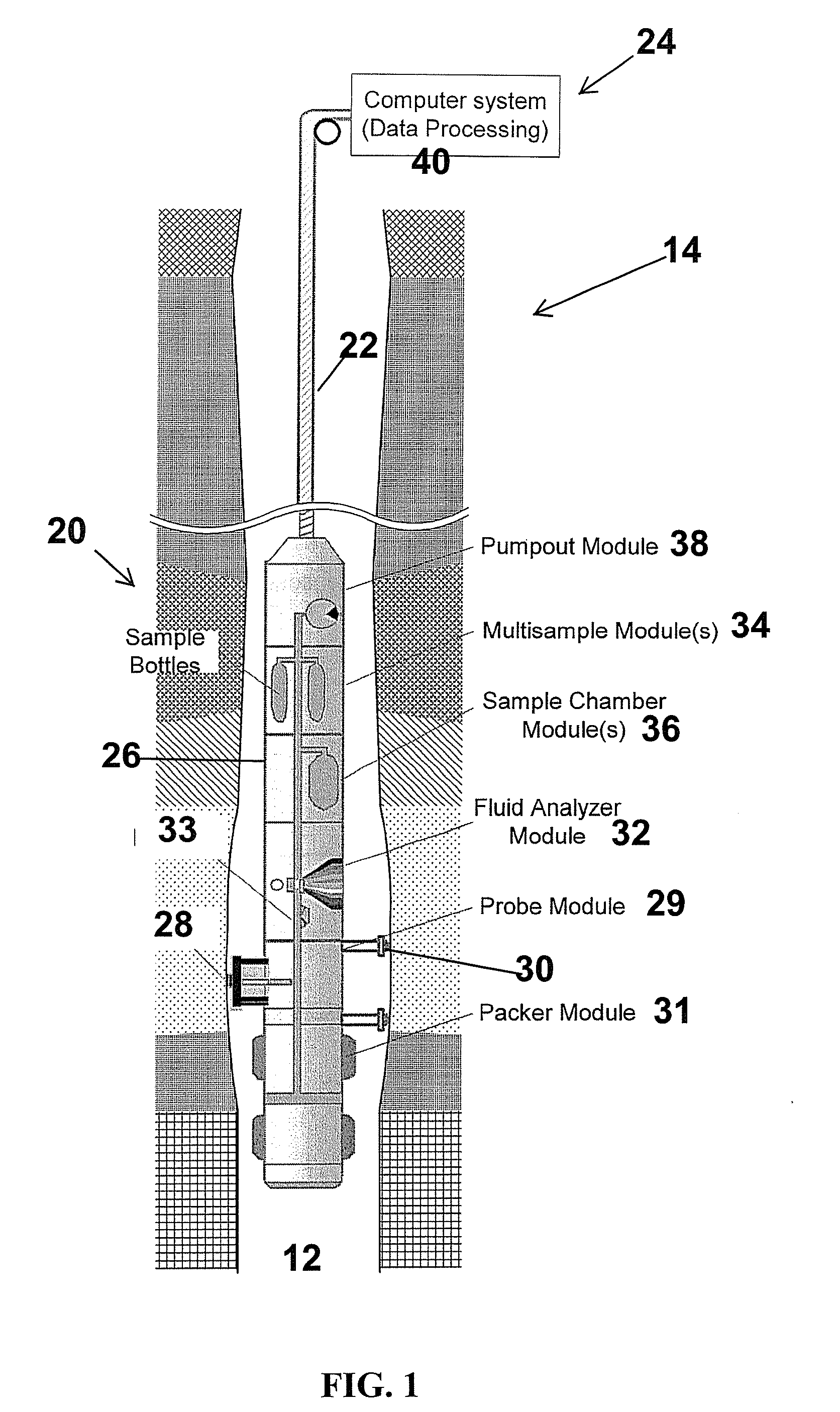
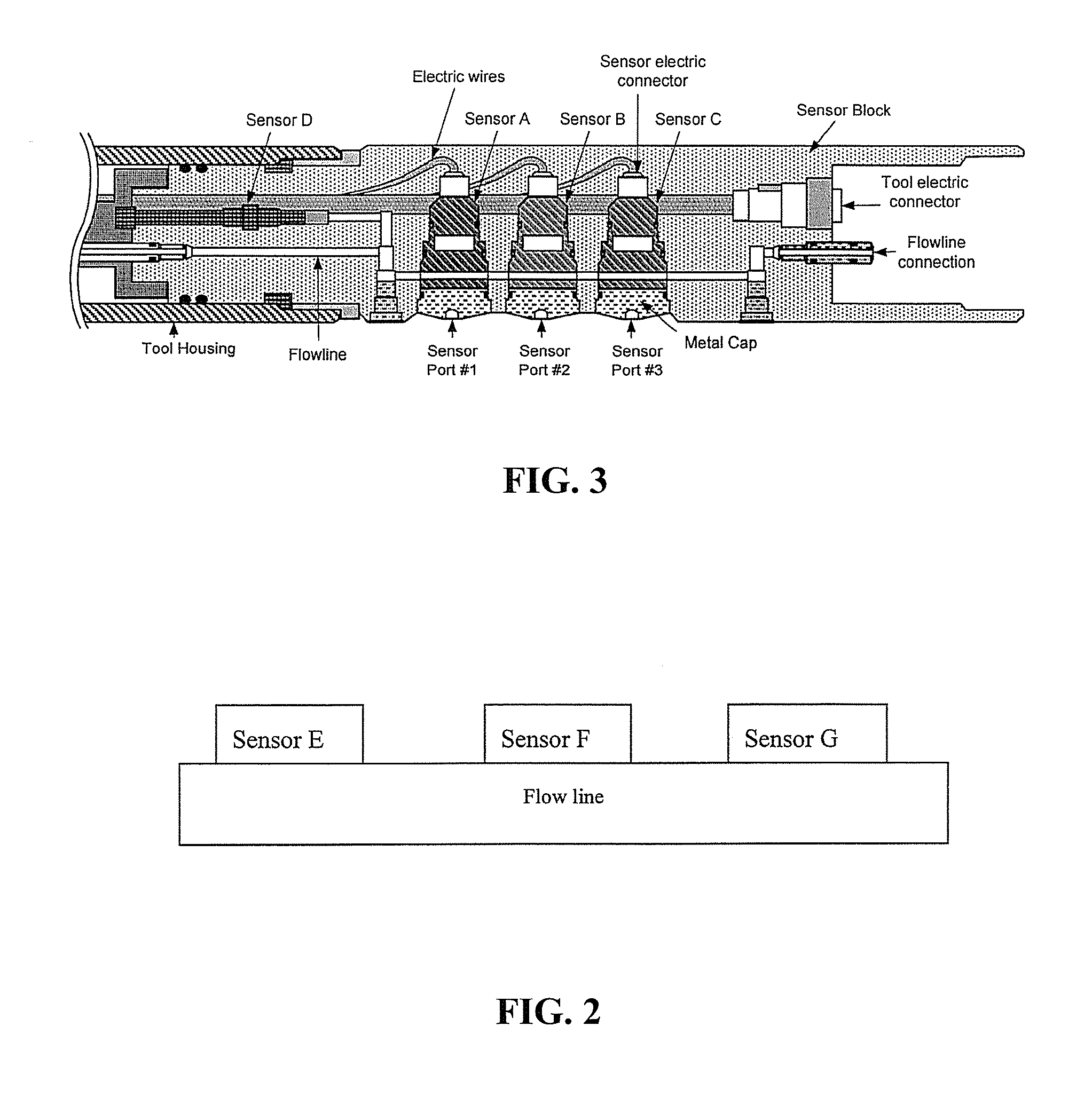
[0010]In consequence of the background discussed above, and other factors that are known in the field of downhole sampling and analysis systems, the present disclosure provides improved sensor system architecture for methods and systems for downhole characterization of geological formations. In particular, some embodiments of the present disclosure provide methods and systems that utilize novel sensor array architecture having plug and play capability and discrete, independent sensor elements with associated communication and control capabilities.
[0012]In other embodiments of the present disclosure, the plug and play architecture disclosed herein provides the capability of using the same type of sensor(s) in various types of tool conveyances without having to modify the tools so that uniformity in data acquisition is possible across different tool systems.

Problems solved by technology

In addition, field testing of new sensor designs is done by building a new tool prototype including the new sensors which adds complexity to new sensor development and testing.
The limitations of conventional systems noted in the preceding are not intended to be exhaustive but rather are among many which may reduce the effectiveness of previously known downhole systems.

Method used


Image

  • Downhole sensor systems and methods thereof
  • Downhole sensor systems and methods thereof
  • Downhole sensor systems and methods thereof

Examples


Embodiment Construction

[0031]Illustrative embodiments and aspects of the invention are described below. It will of course be appreciated that in the development of any such actual embodiment, numerous implementation-specific decisions must be made to achieve the developers' specific goals, such as compliance with system-related and business-related constraints, that will vary from one implementation to another. Moreover, it will be appreciated that such development effort might be complex and time-consuming, but would nevertheless be a routine undertaking for those of ordinary skill in the art having the benefit of this disclosure.

[0032]Reference throughout the specification to “one embodiment,”“an embodiment,”“some embodiments,”“one aspect,”“an aspect,” or “some aspects” means that a particular feature, structure, method, or characteristic described in connection with the embodiment or aspect is included in at least one embodiment of the present invention. Thus, the appearance of the phrases “in one embo...


PUM


Abstract

A sensor module for a sensing apparatus configured for operation downhole, within a borehole. The sensor module comprises a sensor array having a plurality of sensors to sense selected formation parameters and a control system for selective and independent operation of each sensor of the sensor array. Each sensor of the sensor array is configured or designed as a discrete sensor unit for individual and independent communication and control. Each sensor of the sensor array may have an associated electronics module that provides standardized electronic connectivity with the control system.

Description

RELATED APPLICATIONS[0001]This application claims priority of U.S. Provisional Patent Application Ser. No. 61 / 168,218, filed Apr. 10, 2009 the entire contents of which are incorporated herein by reference.BACKGROUND[0002]The present invention relates to the field of sampling and analysis of geological formations for evaluating and testing the formations for purposes of exploration and development of hydrocarbon-producing wells, such as oil or gas wells. More particularly, the present disclosure is directed to methods and systems utilizing a downhole apparatus having an array of sensors that is configured or designed with discrete, independent sensors having individualized control and communication functionality. In this, the present disclosure provides downhole sensor system architecture for well logging tools utilizing plug and play configurations that are configured or designed for downhole oilfield applications.[0003]Downhole sampling and analysis is an important and efficient in...

Claims


Application Information

Patent Timeline
IPC IPC(8): E21B49/08
CPCE21B49/00E21B49/08
Inventor YAMATE, TSUTOMUTERABAYASHI, TORUVASQUES, RICARDOKANAYAMA, KAZUMASAHOSODA, YUJIBRIQUET, STEPHANE
Owner SCHLUMBERGER TECH CORP
Learn More