Synchronous moving device and image measuring apparatus

a technology of moving device and image measuring device, which is applied in the direction of measuring device, lifting device, instruments, etc., can solve the problems of lowering measurement accuracy, and achieve the effects of preventing the lowering of measurement accuracy, reducing installation space, and reducing the direction of extension of wir

Active Publication Date: 2010-10-14
MITUTOYO CORP
View PDF10 Cites 4 Cited by
  • Summary
  • Abstract
  • Description
  • Claims
  • Application Information

AI Technical Summary

Benefits of technology

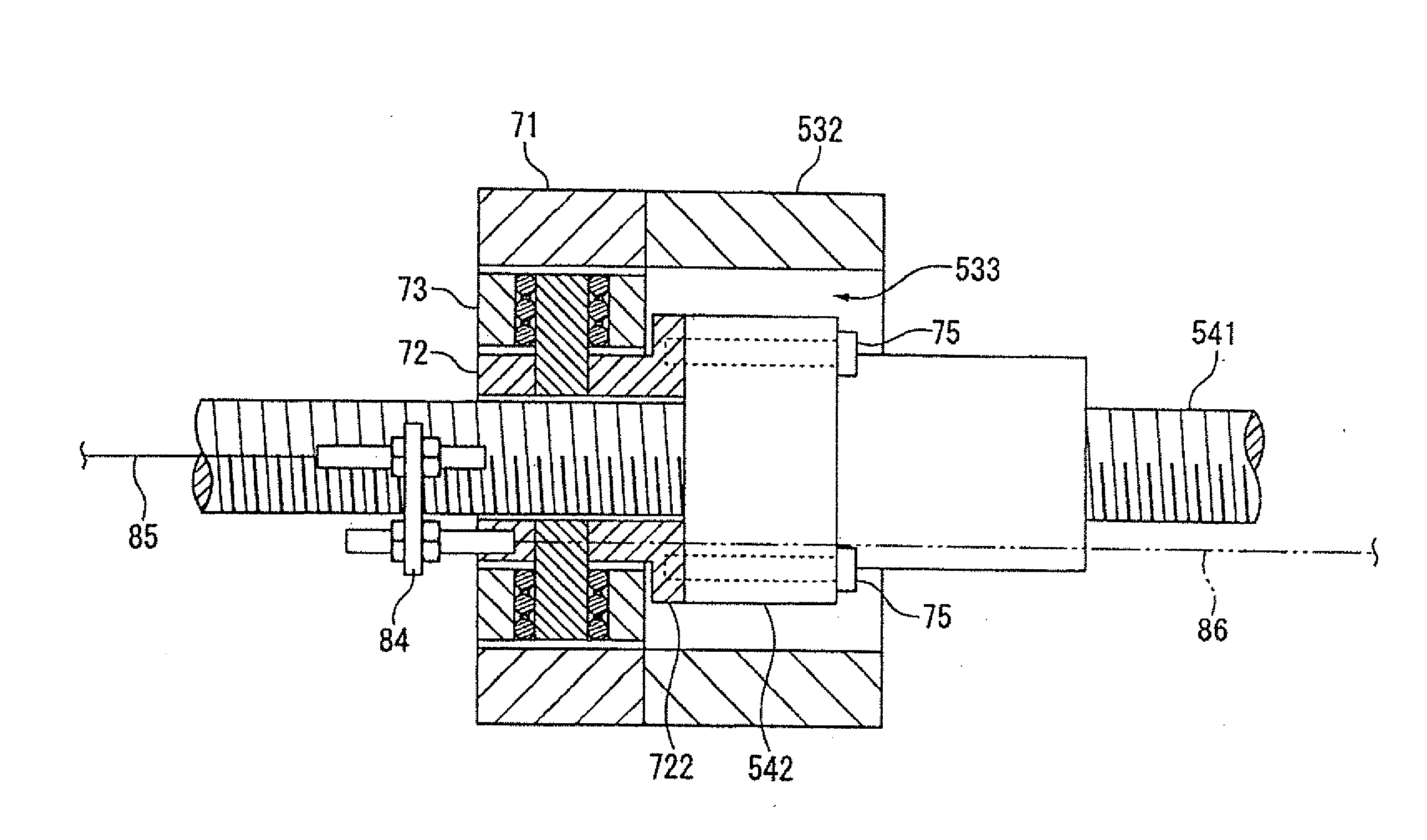
[0011]Since a movable end of the cable binder, that is, the end portion of the cable binder on a side of wiring of the cable into the movable portion, is connected to the second member of the coupler through the connection member, the movable end of the cable binder is also moved following the movement of the movable portion. Even when the behavior of the cable binder accompanying its own movement is transmitted to the second member on this occasion, the intermediate member absorbs the behavior of the cable binder as well as the deflecting motion. Accordingly, the influence of the deflecting motion of the feed screw shaft on the movable portion and the influence of the behavior of the cable binder accompanying its own movement on the movable portion can be suppressed simultaneously. Accordingly, measurement accuracy can be prevented from being lowered.
[0012]The connection member may be a wire. According to this configuration, the direction of extension of the wire can be changed relatively easily when the cable binder and the second member are connected to each other by the wire. Accordingly, the cable binder and the second member can be connected to each other in accordance with the positions of the movable portion and the cable binder relative to the device body. In addition, the space of installation can be reduced, compared with the case where a belt or chain is disposed.
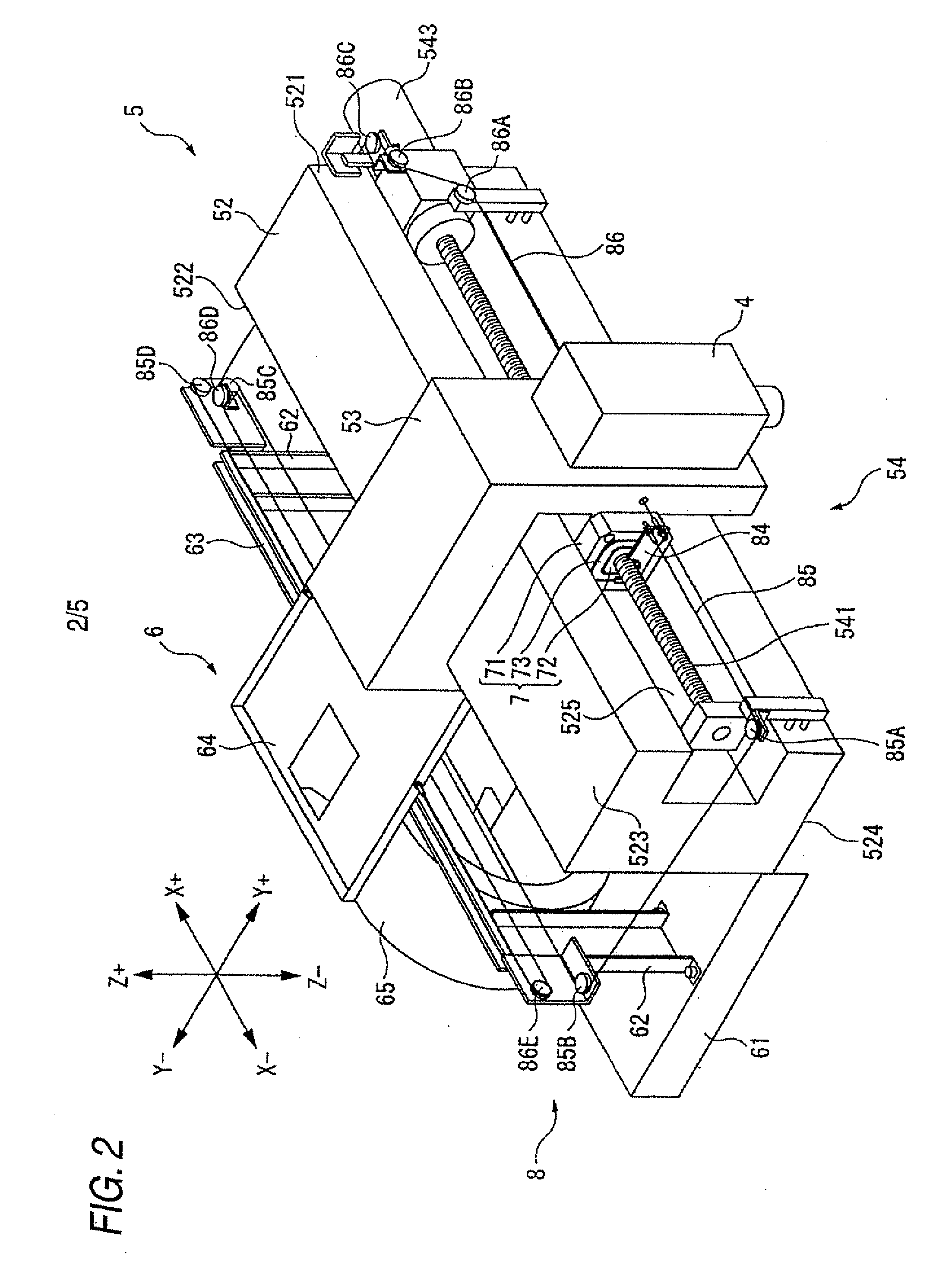
[0013]The synchronous moving device may further includes: a guide rail which is provided on the device body so as to be parallel with a direction of movement of the movable portion; and a support plate which is provided so as to be movable along the guide rail, wherein the end portion of the cable binder is fixed to the support plate. According to the configuration, the direction of movement of the end portion of the cable binder is guided by the support plate and the guide rail, so that the end portion of the cable binder can be slid smoothly because torsion of the cable is rarely generated and the influence of reaction force thereof is a little.
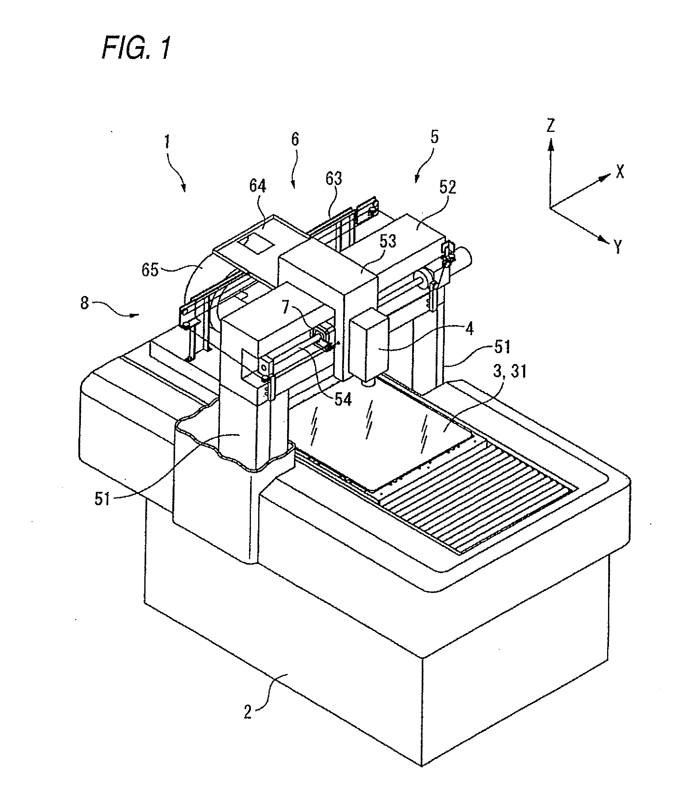
[0014]According to another aspect of the invention, there is provided an image measuring apparatus including: a synchronous moving device comprising: a device body; a movable portion which is provided in the device body so as to be movable; a feed screw shaft which is supported on the device body so as to be rotatable and which moves the movable portion; a nut member which is thread-engaged with the feed screw shaft; a coupler which couples the movable portion and the nut member; and a cable binder which supports and guides a cable wired into the movable portion, wherein: the coupler includes a first member fixed to the movable portion, a second member fixed to the nut member, and an intermediate member interposed between the first and second members for absorbing deflecting motion of the feed screw shaft in a plane orthogonal to an axis of the feed screw shaft; and an end portion of the cable binder on a side of wiring of the cable into the movable portion is connected to the second member through a connection member and moved in synchronization with the movable portion; a stage on which a subject to be measured is put; an image capturing unit which is provided in the movable portion for capturing an image of the subject; and a moving mechanism which moves the subject and the image capturing unit relative to each other, wherein the shape or size of the subject is measured based on data of the image captured by the image capturing unit. In this configuration, when the image capturing unit provided in the movable portion is moved by the feed screw mechanism of the synchronous moving device, the end portion (movable end) of the cable binder can be also moved following the image capturing unit. On this occasion, because both the deflecting motion of the feed screw shaft and the behavior of the cable binder accompanying its own movement are not transmitted to the movable portion by the coupler in the same manner as the synchronous moving device, improvement in measurement accuracy can be attained.

Problems solved by technology

Accordingly, the behavior of Cableveyor accompanying its own movement, such as the influence of torsion of the cable and reaction force thereof, causes lowering of measurement accuracy because the behavior of Cableveyor is transmitted to the movable portion side (image capturing unit side).

Method used


Image

  • Synchronous moving device and image measuring apparatus
  • Synchronous moving device and image measuring apparatus
  • Synchronous moving device and image measuring apparatus

Examples


Embodiment Construction

[0021]An embodiment of the invention is an example in which the invention is applied to an image measuring apparatus.

[0022]As shown in FIG. 1, an image measuring apparatus 1 according to the embodiment includes a pedestal 2, a stage 3, an optical device 4, a moving mechanism 5, a cable support mechanism 6, and a synchronizing mechanism 8. The pedestal 2 serves as a body of the apparatus. The stage 3 is provided on an upper surface of the pedestal 2 so as to be movable in a Y-axis direction. A subject to be measured is put on the stage 3. The optical device 4 serves as an image capturing unit which captures an image of the subject. The moving mechanism 5 moves the optical device 4 in two-dimensional directions (an X-axis direction and a Z-axis direction). The cable support mechanism 6 supports and guides a cable through which electric power is fed to the optical device 4 and signals (such as control, image data, etc.) are exchanged with the optical device 4. The synchronizing mechani...


PUM


Abstract

A synchronous moving device includes: a device body; a movable portion which is provided in the device body; a feed screw shaft which is supported on the device body; a nut member which is thread-engaged with the feed screw shaft; a coupler which couples the movable portion and the nut member; and a cable binder which supports and guides a cable wired into the movable portion, wherein: the coupler includes a first member fixed to the movable portion, a second member fixed to the nut member, and an intermediate member interposed between the first and second members for absorbing deflecting motion of the feed screw shaft; and an end portion of the cable binder on a side of wiring of the cable into the movable portion is connected to the second member through a connection member and moved in synchronization with the movable portion.

Description

CROSS-REFERENCE TO RELATED APPLICATIONS[0001]This application is based upon and claims the benefit of priority from Japanese Patent Application No. 2009-097582, filed on Apr. 14, 2009, the entire contents of which are incorporated herein by reference.BACKGROUND[0002]1. Field of the Invention[0003]The present invention relates to a synchronous moving device and an image measuring apparatus.[0004]2. Description of the Related Art[0005]There has been known an image measuring apparatus including a slider which is supported on a body of the apparatus so as to be movable, and an image capturing unit such as a CCD camera which is mounted in the slider, wherein an image of a subject to be measured is captured by the image capturing unit moved relative to the subject so that the shape or size of the subject is measured based on data of the captured image (e.g. see JP-A-2006-266748).[0006]In such an image measuring apparatus, it is necessary to wire a cable into the movable slider for the pur...

Claims


Application Information

Patent Timeline
Patent Type & Authority Applications(United States)
IPC IPC(8): B66F3/08
CPCG01B11/24
Inventor NISHITSUJI, YUTAKAKIMURA, YOSHIHARU
Owner MITUTOYO CORP
Why Eureka
Try Eureka