Motor vehicle

Active Publication Date: 2010-10-14
FORD GLOBAL TECH LLC
View PDF5 Cites 0 Cited by
  • Summary
  • Abstract
  • Description
  • Claims
  • Application Information

AI Technical Summary

Benefits of technology

[0012]Each flap may be pivotally connected to a support member to allow the flap to rotate from the stowed position to the deployed position.

Problems solved by technology

It is a disadvantage of such prior art mechanisms that the roof is stowed in a luggage area of the motor vehicle, thereby reducing the space available for the transport of luggage when the roof is stowed.
It is a further problem with this type of mechanism that it can only be used for motor vehicles having a separate luggage compartment and luggage compartment cover and is not suitable for use with a hatchback type of vehicle.

Method used


Image

  • Motor vehicle
  • Motor vehicle
  • Motor vehicle

Examples


first embodiment

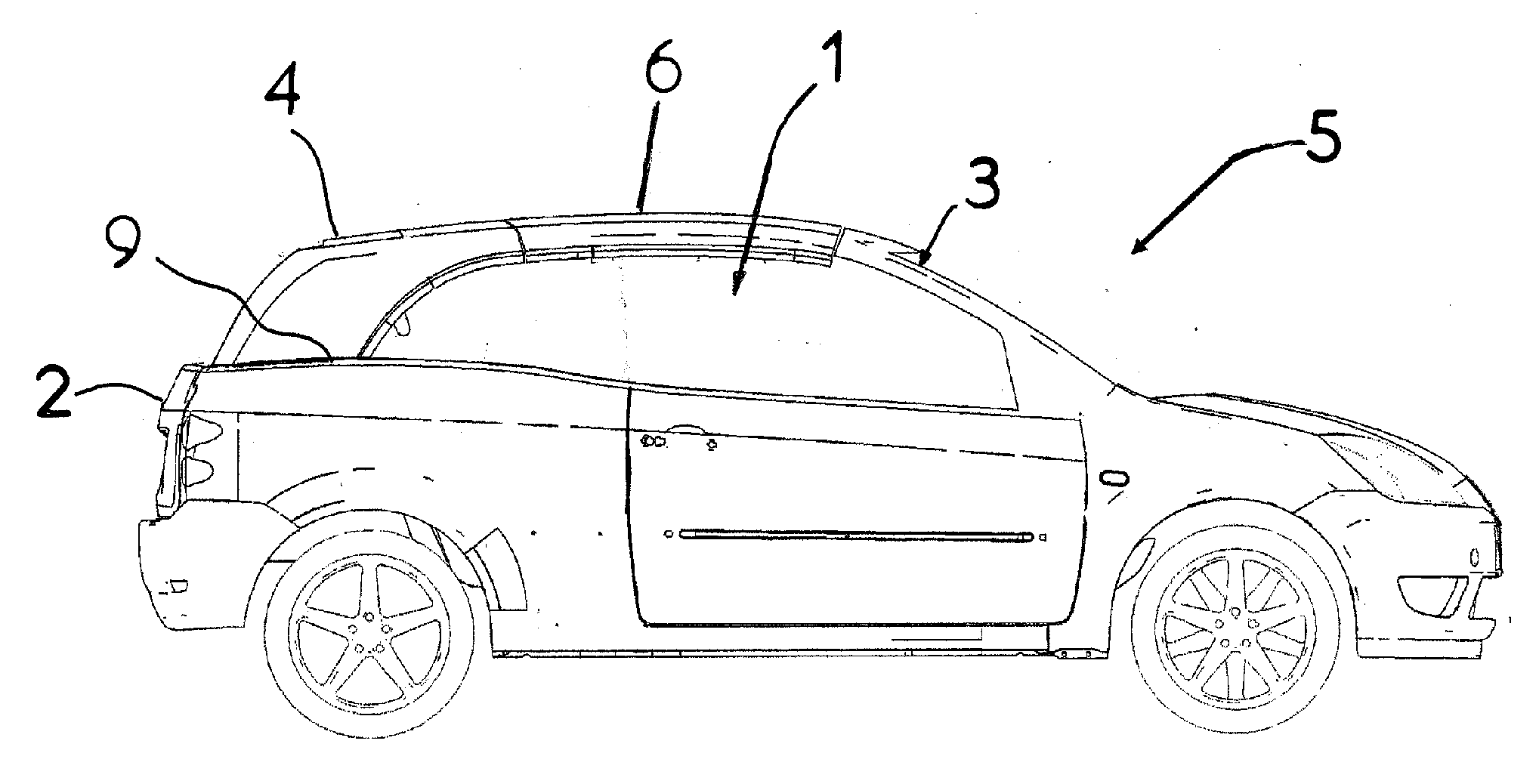
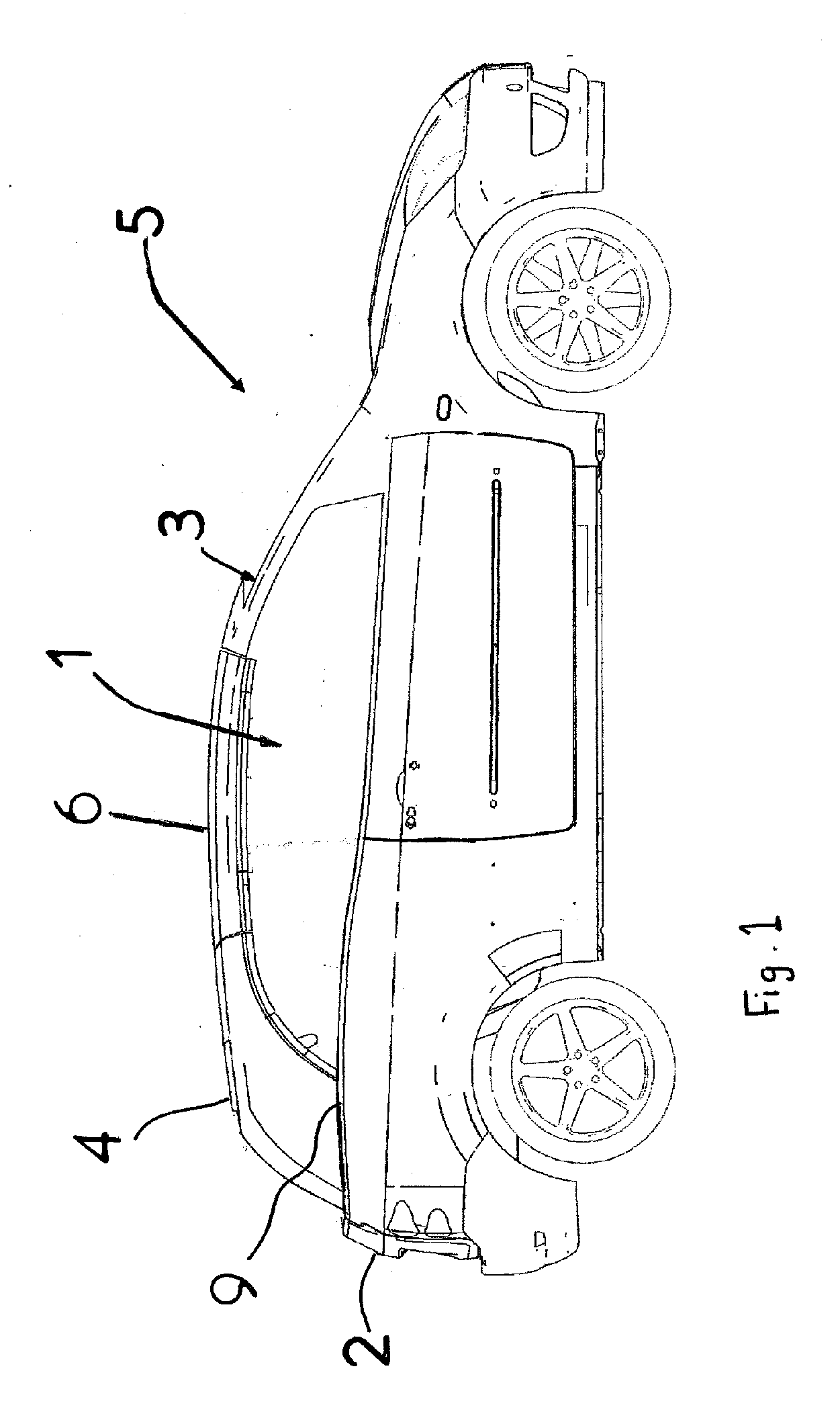
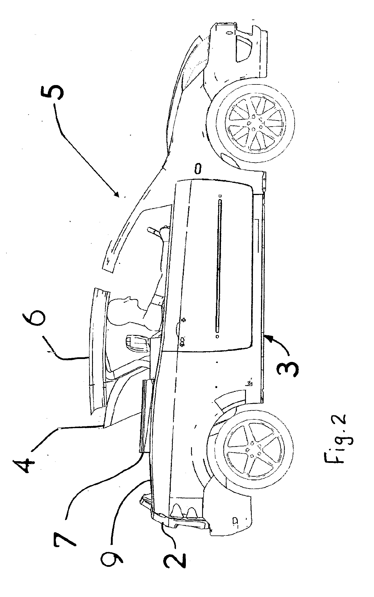
[0045]With reference to FIGS. 1 to 11 there is shown a motor vehicle 5 according to the invention. The motor vehicle 5 has a body structure 3 including a pair of rear outer panels 9, one on each side of the motor vehicle 5, a drop down lower tailgate 2, a rear roof member or panel 4 and a front roof member or panel 6. The front and rear roof members 6 and 4 are moveable from raised positions, as shown in FIG. 1, where they form in combination a cover for a combined passenger and luggage compartment 1 to stowed positions, as shown in FIGS. 4 and 5, where a two seat convertible vehicle is formed. FIG. 2 shows an intermediate position in which the front and rear roof members 6 and 4 are partially stowed.

[0046]To stow the two roof members 4 and 6, one of the two roof members 4 and 6 is firstly moved to disengage a rear edge of the front roof member 6 from a front edge of the rear roof member 4. This can be achieved by sliding the rear roof member 4 rearwardly, by providing an inclined s...

second embodiment

[0066]With reference to FIGS. 12 to 17, there is shown the invention which differs from that previously described in that the flap 107 is not stowed between inner and outer panels of the motor vehicle 5 but in a separate stowage compartment located outside the rear panel, and the flap 107 is not actuated by a sliding mechanism as previously described but by a rotating arm arrangement that moves the flap 107 though an arc.

[0067]With reference to FIG. 14 (which is diagrammatic and does not show in detail the actuation mechanism), the flap 107 is shown in its stowed position within a stowage compartment formed by a recess in the rear outer panel 9 and a moveable cover panel 150 pivotally connected at its lower end to an outer surface of the rear outer panel 9. The cavity defined between the outer rear panel 9 and the inner rear panel 8 is not in this case occupied by the flap 107 or its actuating mechanism, and so there is more room for the drop down window 10 to be stowed in the cavit...


PUM


Abstract

A motor vehicle (5) is disclosed having a roof structure comprised of a front roof member (6) and a rear member (4) which together form a cover for a passenger compartment (1) of the motor vehicle (5) when both of the roof members (4, 6) are in respective raised positions. When both of the roof members (4, 6) are lowered into stowed positions to form a convertible vehicle, a flap (7, 107) is deployed on each side of the motor vehicle (5) to bridge a gap between the stowed front roof member (6) and an upper edge of an outer rear panel (9).

Description

BACKGROUND OF THE INVENTION[0001]1. Field of the Invention[0002]This invention relates to motor vehicles and in particular to a motor vehicle having a roof structure that can be stowed away to form an open top vehicle.[0003]2. Related Art[0004]It is known, for example, from French Patent Publication FR-2856014 and German Patent Publication DE-19948746 to provide a motor vehicle having a roof structure which can be stowed away to convert the motor vehicle into an open top vehicle.[0005]It is a disadvantage of such prior art mechanisms that the roof is stowed in a luggage area of the motor vehicle, thereby reducing the space available for the transport of luggage when the roof is stowed. It is a further problem with this type of mechanism that it can only be used for motor vehicles having a separate luggage compartment and luggage compartment cover and is not suitable for use with a hatchback type of vehicle.[0006]It would be desirable to provide a motor vehicle in which the roof can ...

Claims


Application Information

Patent Timeline
IPC IPC(8): B60J7/20
CPCB60J7/148B60J7/203B60J7/201B60J7/143B60J7/20
Inventor CONDON, ALAN RICHARDHARDING, JOHN K.GERHARDT, TORSTEN
Owner FORD GLOBAL TECH LLC
Why Eureka
Try Eureka