Temporal affinity analysis using reuse signatures

Inactive Publication Date: 2008-04-08
UNIVERSITY OF ROCHESTER
View PDF7 Cites 19 Cited by
  • Summary
  • Abstract
  • Description
  • Claims
  • Application Information

AI Technical Summary

Benefits of technology

[0018]Reference affinity gives a unique and hierarchical partition of all data. The present invention has rigorous properties owing to its direct link, k, to the affinity definition. Experiments have shown that the new method reveals a rich affinity relationship among program data, which forms a hierarchy of detailed layers with a different but intuitive dis

Problems solved by technology

Second, reuse distances reveal

Method used


Image

  • Temporal affinity analysis using reuse signatures
  • Temporal affinity analysis using reuse signatures
  • Temporal affinity analysis using reuse signatures

Examples


Example

[0029]A preferred embodiment of the invention and uses thereof will now be set forth in detail with reference to the drawings.

[0030]Approximate Reuse Distance Analysis

[0031]In a distance analysis, program execution is viewed as a sequence of accesses to data. Measuring reuse distance between two data accesses means counting the number of distinct data between them. In the worst case, the measurement needs to examine all preceding accesses for each access in the trace. So a naive algorithm would need O (N2) time and O (N) space for a trace of length N. This cost is impractical for real programs, which have up to hundreds of billions of memory accesses.

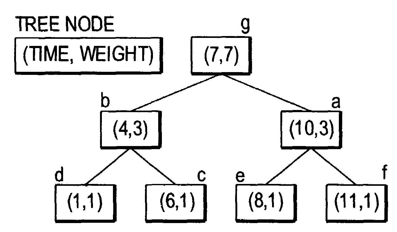
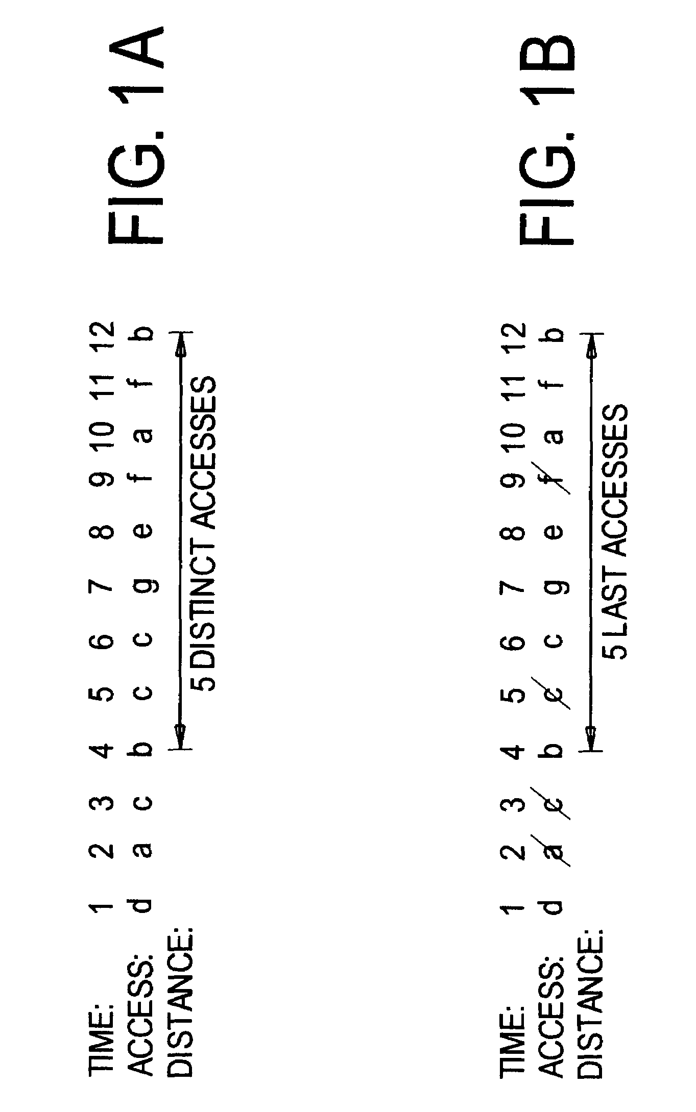
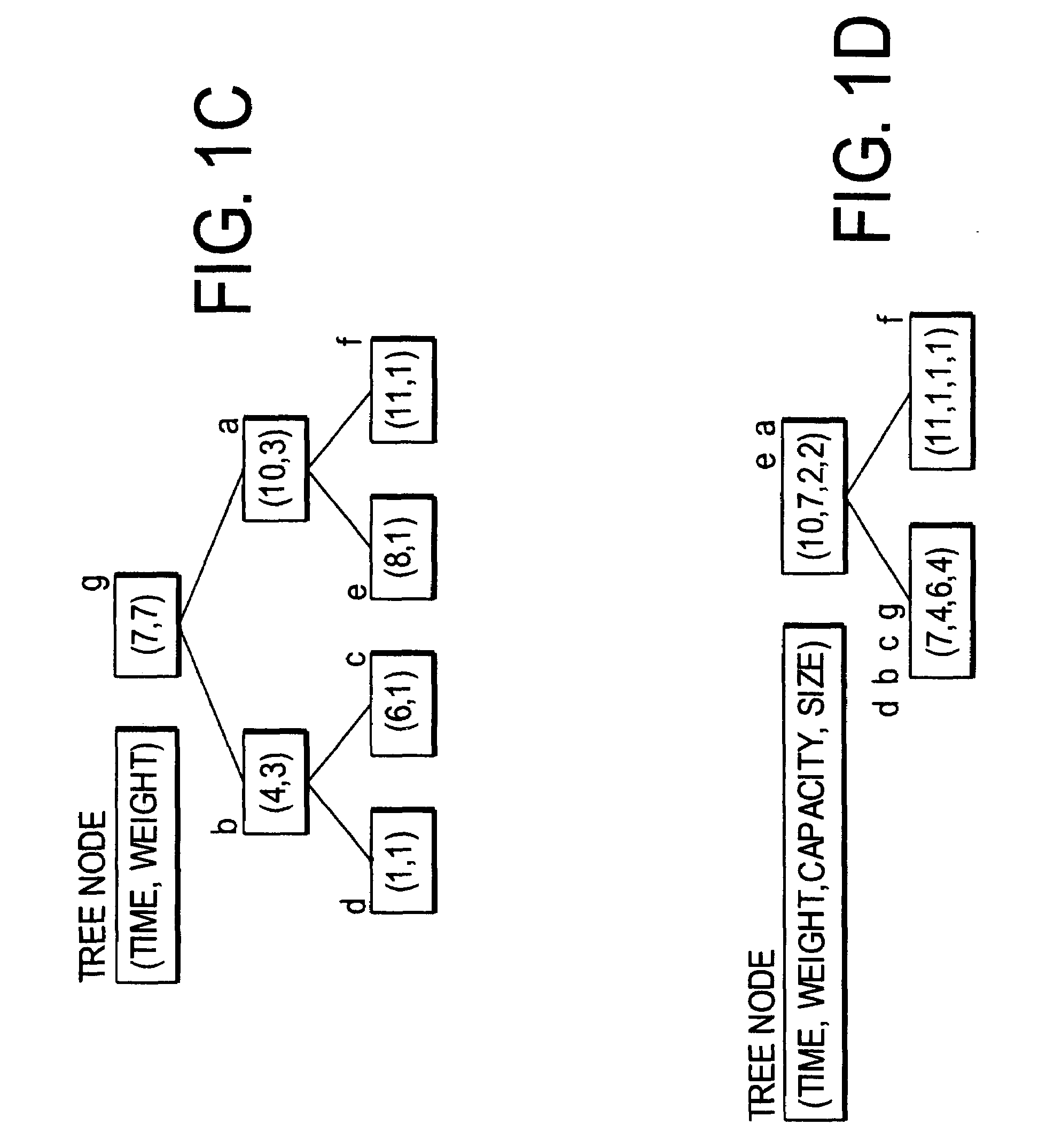
[0032]The time and space costs can be improved, as shown by the example in FIGS. 1A-1D. FIG. 1A shows that it is necessary to count accesses to distinct data. As shown, the reuse distance between two b's is 5. FIG. 1B shows that instead of storing the whole trace, one can store (and count) just the last access of each datum.

[0033]FIG. 1...


PUM


Abstract

Reuse distance is the number of data which are accessed between accesses of a datum. The computation of reuse distance uses a search tree and is carried out through approximate analysis, pattern recognition, or distance-based sampling. The reuse distance can be used to detect reference affinity, that is, to detect which data are accessed together.

Description

REFERENCE TO RELATED APPLICATION[0001]The present application claims the benefit of U.S. Provisional Patent Application No. 60 / 437,435, filed Jan. 2, 2003, whose disclosure is hereby incorporated by reference in its entirety into the present disclosure.FIELD OF THE INVENTION[0002]The present invention is directed to a technique for analyzing data reuse in computing systems and more particularly to such a technique in which the reuse patterns of various data are analyzed together for grouping of the data or like purposes.DESCRIPTION OF RELATED ART[0003]While the memory of most machines is organized as a hierarchy, program data are laid out in a uniform address space. All current PCs and workstations use cache blocks of at least 64 bytes, making the utilization an important problem. If only one word is useful in each cache block, a cache miss will not serve as a prefetch for other useful data. Furthermore, the program would waste up to 93% of memory transfer bandwidth and 93% of cache...

Claims


Application Information

Patent Timeline
IPC IPC(8): G06F9/44G06F12/00G06F9/45G06FG06F11/30G06F12/08G06F17/30
CPCG06F8/4442G06F11/3466G06F12/0862G06F2201/885
Inventor DING, CHENZHONG, YUTAO
Owner UNIVERSITY OF ROCHESTER
Why Eureka
Try Eureka