Clamping apparatus for clamping at least two component parts

Active Publication Date: 2010-06-10
LPKF LASER & ELECTRONICS
View PDF5 Cites 7 Cited by
  • Summary
  • Abstract
  • Description
  • Claims
  • Application Information

AI Technical Summary

Benefits of technology

[0011]narrow connecting struts to connect the inner clamping fixture with the outer clamping chuck, which bridge the gap in the clamping chuck that allows the beam path to pass from the machine to the components.
[0012]The invention proposes an inner clamping technology that has not been used until now in laser-based machines because of the shadowing effects connected with the clamping parts lying inside. In this light, the invention resulted from the discovery that marginal interruptions of the laser beam, such as those caused by the small connecting struts that fasten the inner clamping fixture to the exterior clamping chuck, are not appreciably detrimental to the weld seam. Because o

Problems solved by technology

This can also result in pulse time r

Method used


Image

  • Clamping apparatus for clamping at least two component parts
  • Clamping apparatus for clamping at least two component parts
  • Clamping apparatus for clamping at least two component parts

Examples


Example

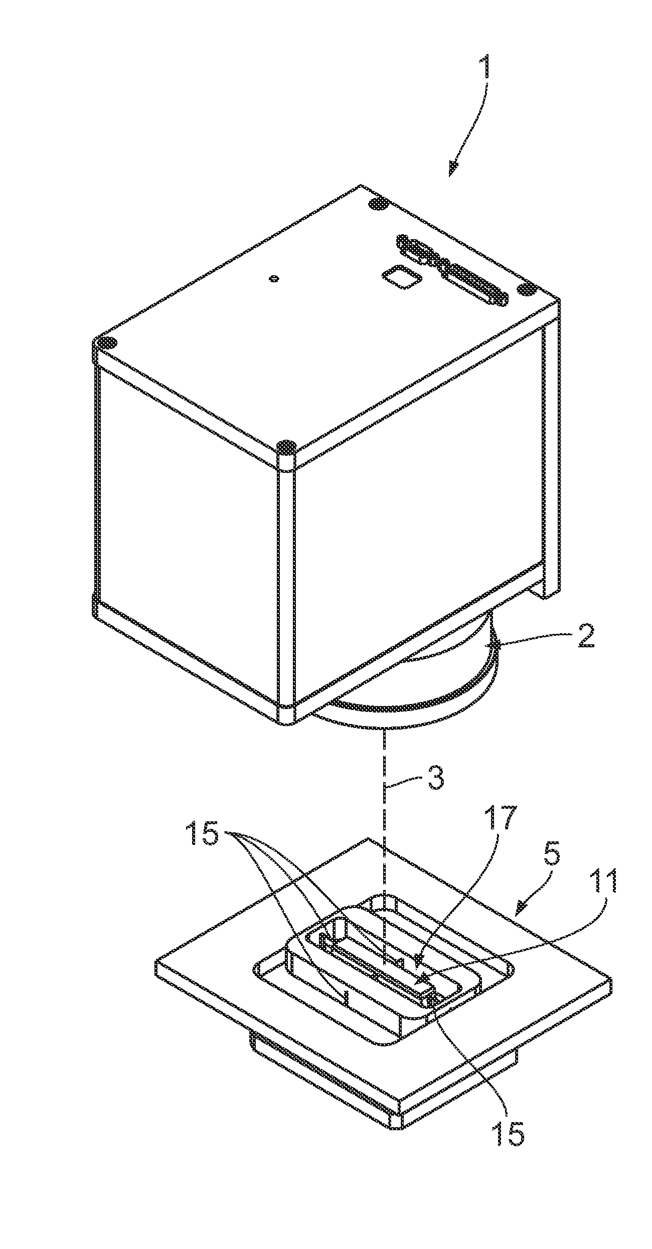
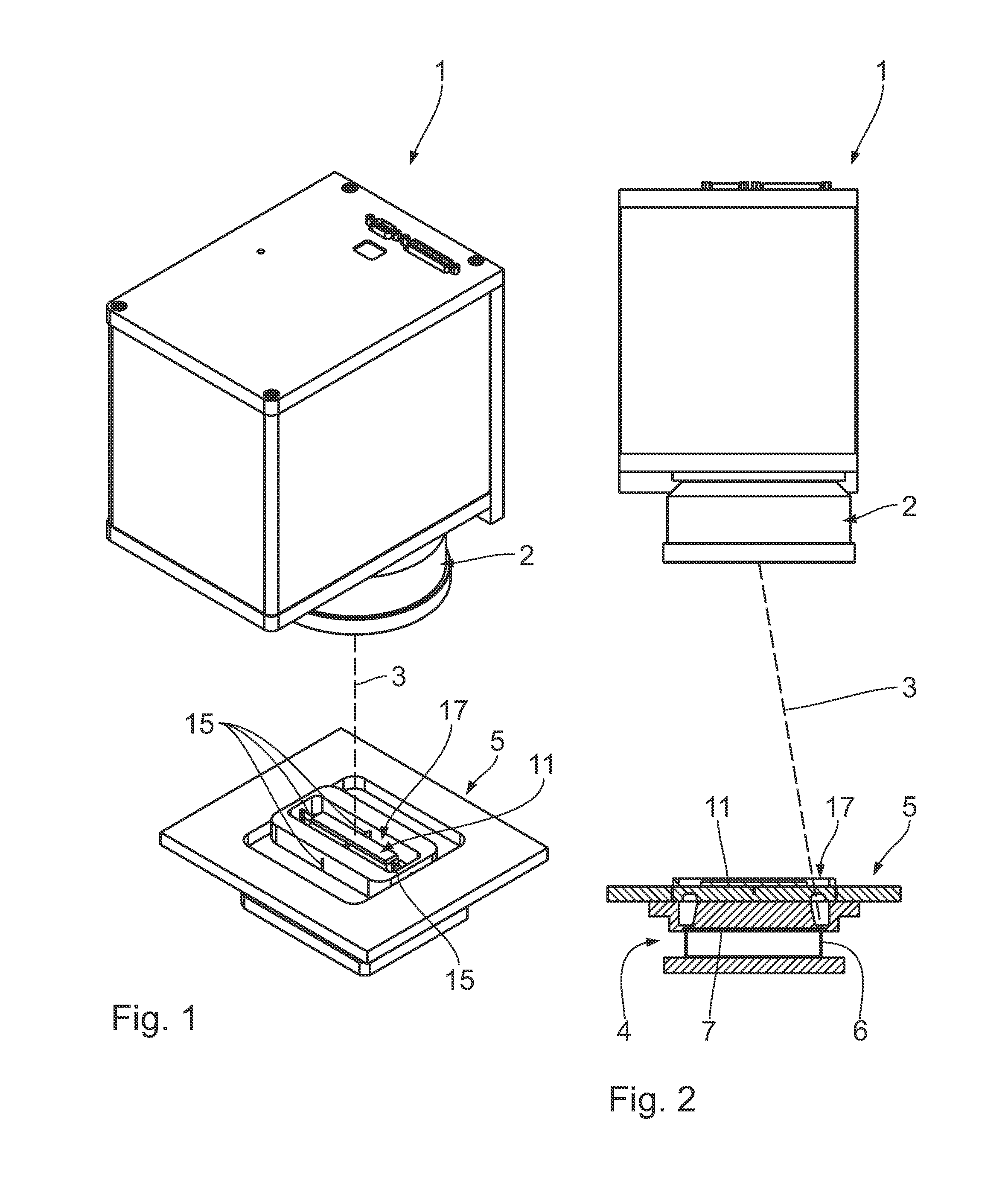
[0023]As FIGS. 1 and 2 make clear, a laser welding device is made up of a laser welding head, denoted as a whole with 1, which is state-of-the-art in its construction and as such must not be further described. The laser welding head 1 may be designed as a scanner system or as a moveable contour welding head.

[0024]Through a scanning device the laser beam marked with dashes in FIG. 2 passes over a defined beam path (see FIGS. 3 and 6) to process the workpiece held by the clamping apparatus, which will be described below.

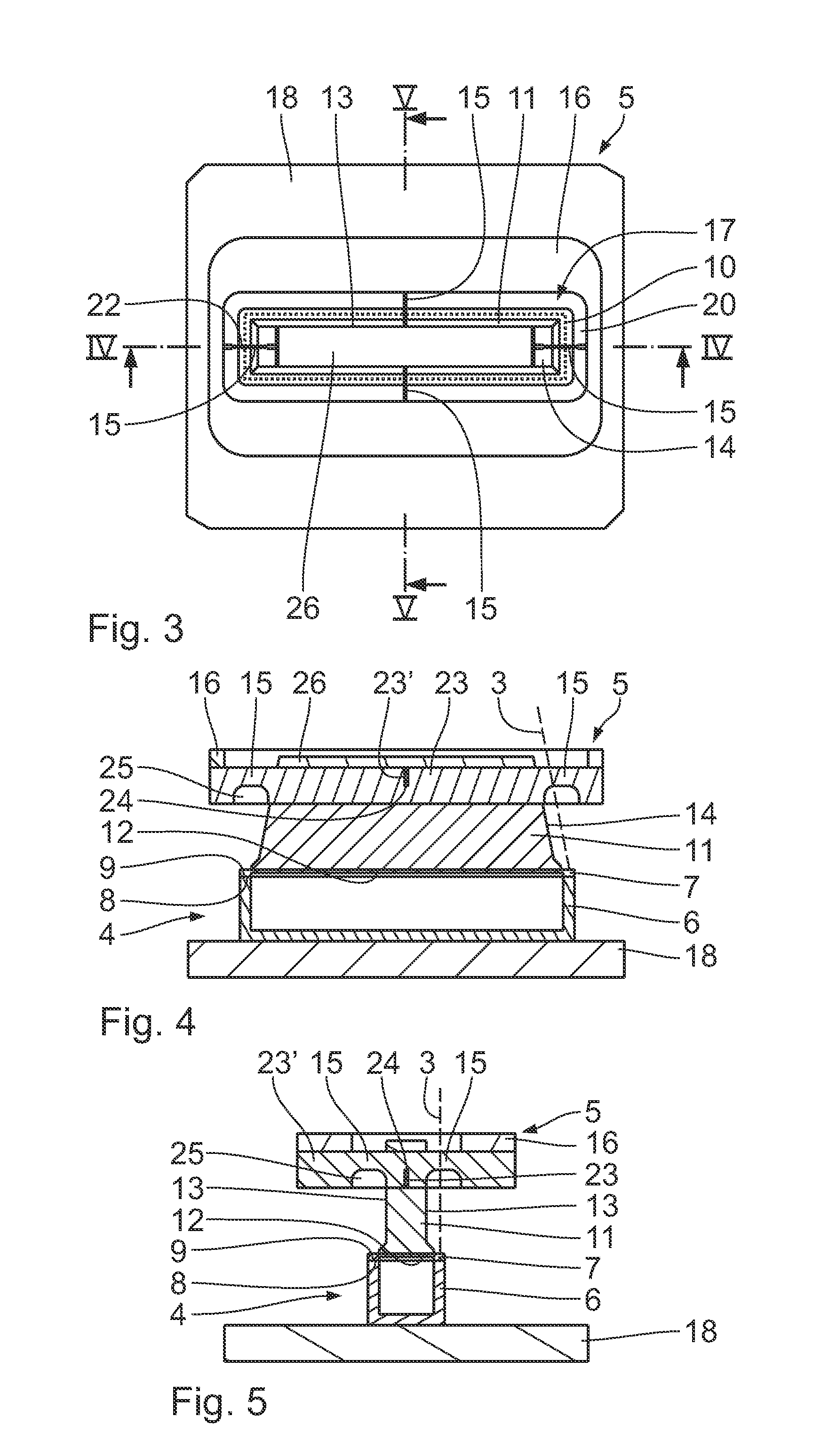
[0025]FIGS. 3 to 5 demonstrate the configuration of a clamping apparatus for the exclusive inner clamping of the workpiece. The workpiece is made up of two components: one cuboid, top-open lower component and a lid that sits on top and is flush with the outer walls of the lower component. The latter is made up of a transmissive thermoplastic material for the wavelength of the laser beam, whereas the lower component is made of a laser-beam-absorbing and heat-transformab...


PUM

PropertyMeasurementUnit
Pressureaaaaaaaaaa
Shapeaaaaaaaaaa
Areaaaaaaaaaaa

Abstract

The invention relates to a clamping device for clamping at least two components (6, 7) in a radiation-protected machine tool, particularly in a laser welding device (1), comprising—a receptacle (18) for supporting the first component (6), —a clamping head (16) for applying a force to the second component (7) in order to generate clamping pressure at the joint surface (8, 9) between the two components (6, 7), —an inner clamping jaw (11) located within the peripheral beam path (10) of the machine tool, the jaw having a clamping surface (12) for internally clamping the components (6, 7), and—narrow connecting struts (15) for connecting the inner clamping jaw (11) to the external clamping head (16), said connecting struts (15) bridging the passage gap (7) in the clamping head (16) allowing access for the beam path (10) of the machine tool to the components (6, 7).

Description

FIELD OF THE INVENTION[0001]The invention pertains to a clamping apparatus for clamping at least two component parts in a laser-based machine tool, especially in a laser welding device.BACKGROUND ART[0002]This type of clamping apparatus is known from a variety of printed publications. For example, DE 199 24 469 A1 shows a welding bracket for workpieces, especially for the laser transmission welding of faying surfaces made of plastic, where the faying surfaces are found on the circumferential lip around the edges of the two-part workpiece. One workpiece is held by a carrier for the suspension of the component. The second component is applied with a clamping chuck, which is held outside of the actual welding line for the application of clamping pressure to the faying surface.[0003]For welding devices as per DE 95 10 493 A1, a pressure effect is caused by hydraulic, pneumatic, rolling or other downholders. Explicitly a pressure roller is released, which runs along the radiated area nex...

Claims


Application Information

Patent Timeline
IPC IPC(8): B23K26/10
CPCB23K26/023B23K26/422B23K37/0435B29C65/1635B29C65/1654B29C65/7841B29C66/53461B29K2101/12B29C66/24245B29C66/81267B29C65/00B29C66/8322B29C66/8324B23K26/037B29C66/7392B23K26/702B29C66/24244B29C66/112B29C66/114B29C66/131B29C66/652B29C66/81463B23K26/10B29C65/16B23B31/10
Inventor BRUNNECKER, FRANKALDEBERT, HOLGERKRAUS, ANDREAS
Owner LPKF LASER & ELECTRONICS
Why Eureka
Try Eureka