
Battery monitoring and control system and method of use

a battery monitoring and control system technology, applied in the direction of battery/fuel cell control arrangement, electric devices, electrochemical generators, etc., can solve the problems of battery system shutdown, serial communication failure of each battery monitor chip on the serial chain, etc., and achieve the effect of reducing system functionality and system functionality

Active Publication Date: 2010-10-14
FORD GLOBAL TECH LLC
View PDF16 Cites 86 Cited by
  • Summary
  • Abstract
  • Description
  • Claims
  • Application Information

AI Technical Summary

Benefits of technology

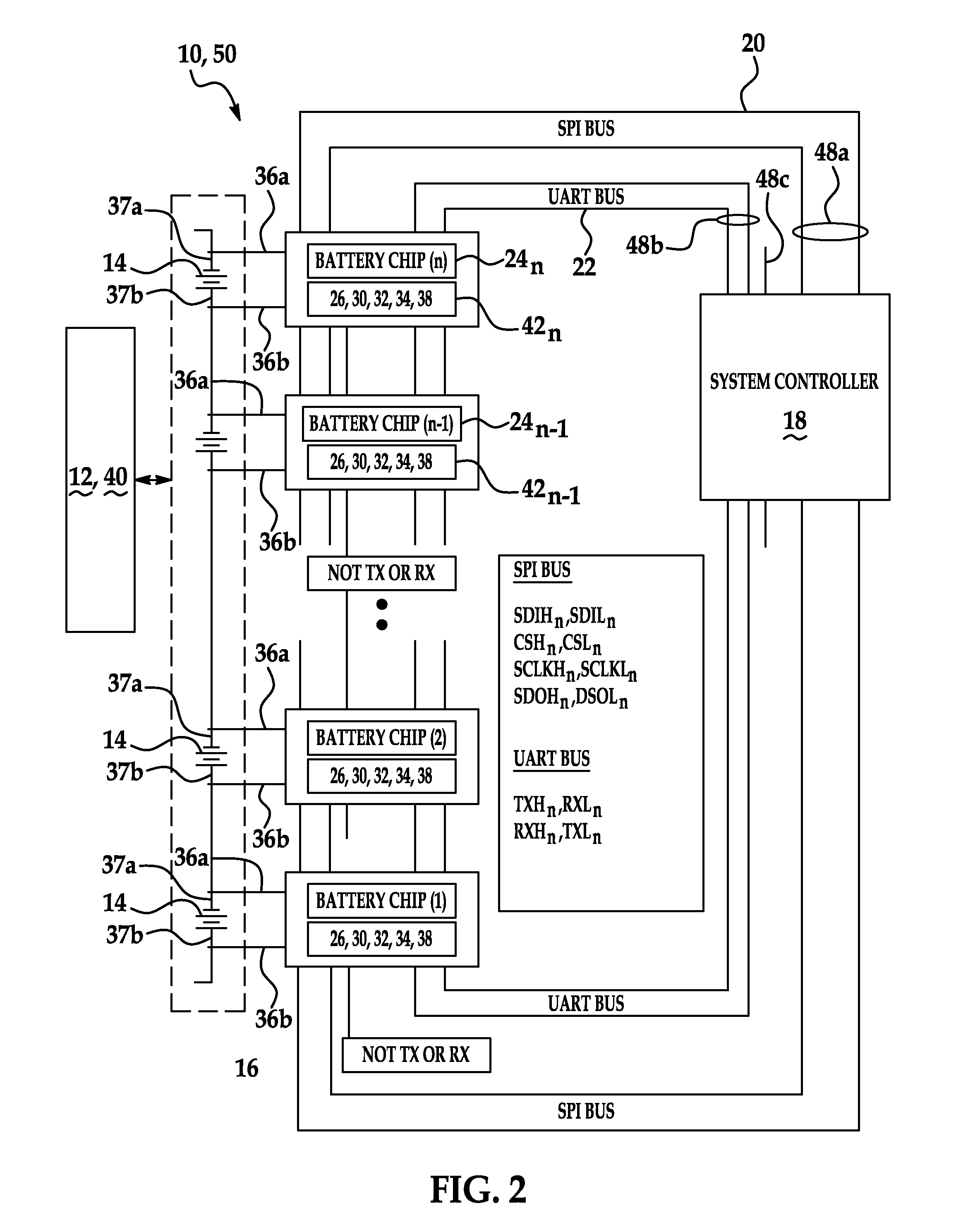
[0017]A method of monitoring and controlling the battery monitor and control system includes performing a self-test of the system to determine system functionality; determining functionality of a primary serial communication link; determining functionality of a redundant secondary serial communication link; selecting a communication link from the primary or the secondary serial communication link to communicate between one or more battery monitor modules and a system controller; providing notification to a user if system functionality is reduced; and implementing a limited operation strategy (LOS) if the system functionality is reduced.

Problems solved by technology

Battery electronics for batteries associated with electric or hybrid vehicles present several challenges in managing the connections between batteries, as well as monitoring and managing battery output.
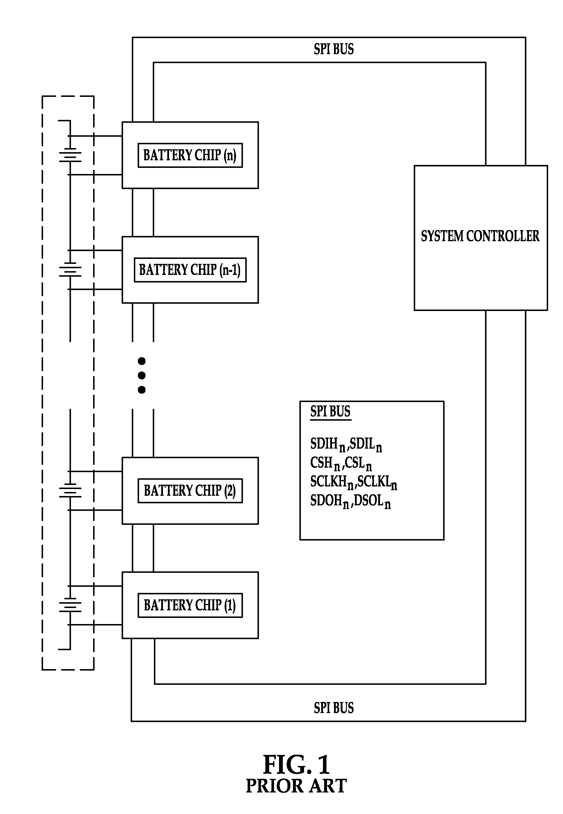
However, by using the “serial daisy chain,” a circuit in the battery system is created whereby if any of the electrical connections included in the serial link between each respective battery monitor chip of the plurality of battery monitor chips in a “serial daisy chain” form an open-circuit or a short-circuit to an adjacent node, then serial communication fails for each battery monitor chip on the serial chain.
Without a redundant communication link between each battery monitor chip of the plurality of battery monitor chips, a failure in the serial link between each battery monitor chip may result in the shutdown of the entire battery system.

Method used


Image

  • Battery monitoring and control system and method of use
  • Battery monitoring and control system and method of use
  • Battery monitoring and control system and method of use

Examples


Embodiment Construction

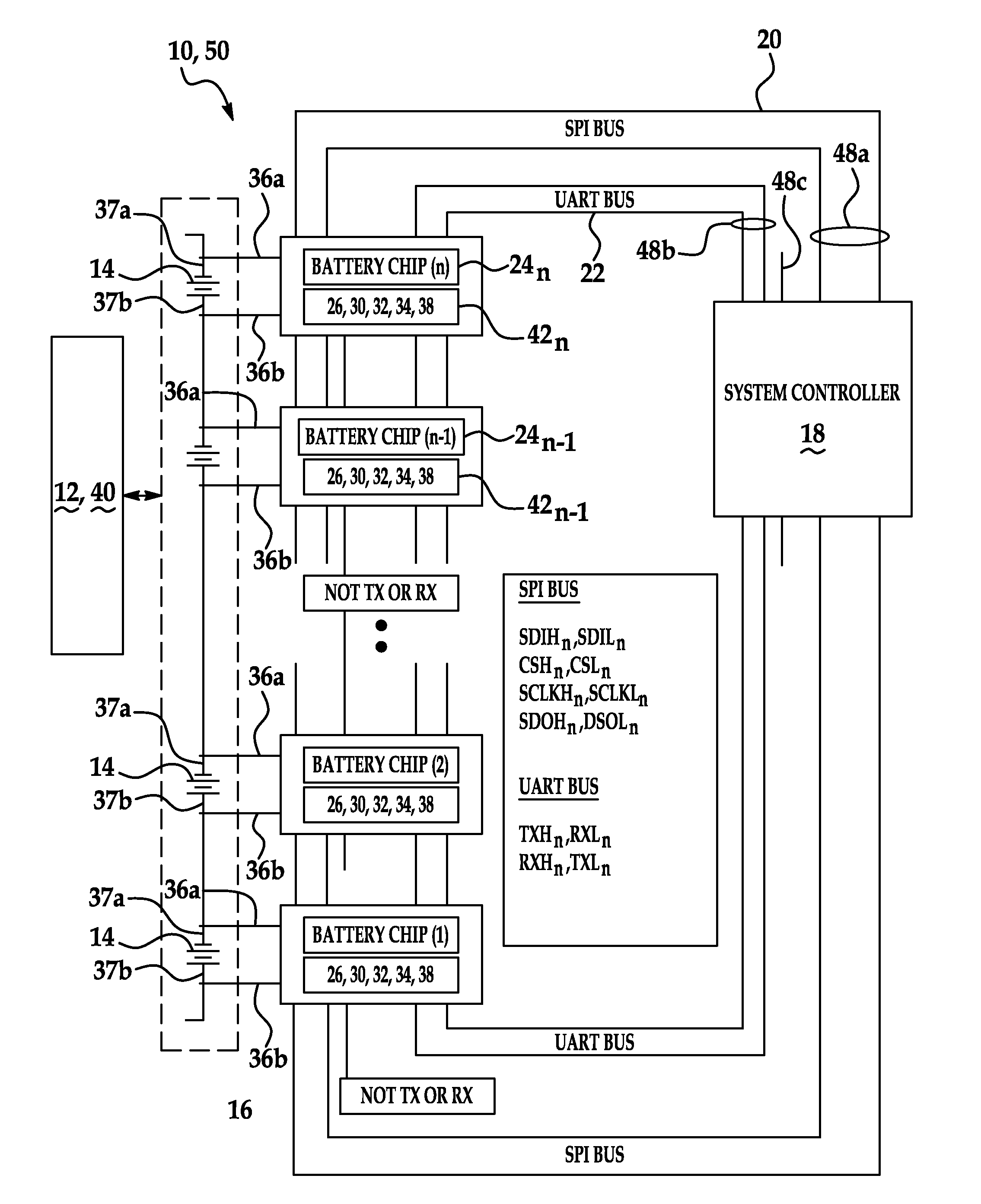
[0018]The battery monitoring and control system and method of use of the invention disclosed herein provides a more robust commutation interface compared to special purpose hardware pins provided to backup a primary communication interface that are known in the art. The system and method provides a redundant and independent symmetric secondary serial bus in addition to a primary serial bus. Additionally, no two serial communication pins from an interface in operative communication with an associated one of a primary or a secondary serial bus are directly adjacent thereby allowing for continuous battery operation when a single pin in a series of battery monitoring modules becomes non operational failed. Additionally, the battery system remains operational when an open or short circuit occurs in only one of either the primary or secondary serial bus.

[0019]Referring now to the drawings, in particular FIG. 1. FIG. 1 illustrates a prior art system of placing a plurality of battery monito...


PUM


Abstract

A battery monitoring and control system and method of monitoring and controlling provides a redundant and independent symmetric secondary serial bus in addition to a primary serial bus within a battery monitoring and control system that includes a plurality of battery monitoring modules and associated IC battery monitor chips in serial communication with a system controller. Additionally, no two serial communication pins from an interface in operative communication with an associated one of a primary or a secondary serial bus are directly adjacent thereby allowing for continuous battery operation when a single pin in a series of battery monitoring modules becomes non operational failed. Additionally, the battery system remains operational when an open or short circuit occurs in only one of either the primary or secondary serial bus.

Description

FIELD OF THE INVENTION[0001]The present invention relates generally to monitoring and controlling a battery system and providing a link between a plurality of batteries and more particularly to a method of monitoring a redundant link between batteries and associated integrated circuit (IC) battery modules.BACKGROUND OF THE INVENTION[0002]Battery electronics for batteries associated with electric or hybrid vehicles present several challenges in managing the connections between batteries, as well as monitoring and managing battery output. Existing IC battery monitor chip architecture includes either a serial or a parallel communication link from the battery monitor chip to a system controller, the system controller coordinating all battery monitor chips in a system and gathering data therefrom while also controlling charge balancing of the individual batteries.[0003]As electric or hybrid vehicles typically include a plurality of batteries, these individual batteries are each managed b...

Claims


Application Information

Patent Timeline
Patent Type & Authority Applications(United States)
IPC IPC(8): H02J7/04
CPCH02J7/0014Y02T10/7055H02J7/0021B60L3/0046H01M10/441B60L2240/547B60L2240/549Y02T90/16H01M10/4207H04Q9/00H04Q2209/30B60L58/18B60L58/12B60L58/21B60L58/22Y02T10/70Y02E60/10H02J7/0047
Inventor TABATOWSKI-BUSH, BEN A.
Owner FORD GLOBAL TECH LLC
Learn More