

Optical Measuring Device and Process
a technology of optical measuring device and optical element, applied in the direction of optical elements, instruments, fluorescence/phosphorescence, etc., can solve the problems of reducing the field of use to a limited set of applications, limiting the envelope performance, and no longer analysing fluorophores individually but treating, etc., to achieve the effect of scanning the sample faster and scanning the sample faster
- Summary
- Abstract
- Description
- Claims
- Application Information
AI Technical Summary
Benefits of technology
Problems solved by technology
Method used
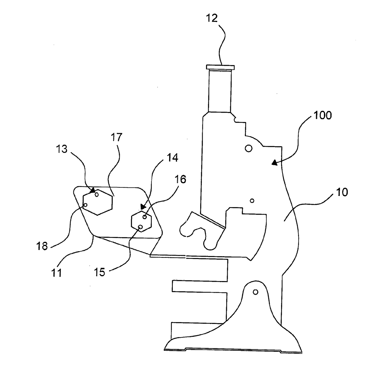
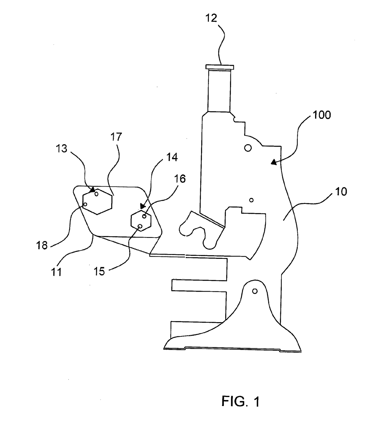
Image

Examples
Embodiment Construction
Light Distributions
Light Distributions Created by Conical Diffraction
[0350]Referring to FIG. 7a, this figure shows the light distribution, created through a conical crystal with a normalized conical parameter ρ0 of 0.388, calculated by a scalar approximation for different input and output polarization states, including at input or output either a circular or linear polarizer or a radial or azimuthal polarizer. These light distributions were calculated in an imaging intermediate plane and not at the focus of the objective to separate the conical refraction from vectorial effects. The input and output states of polarization are characterized by their angle for linear polarizations and their chirality for circular polarizations.
[0351]Referring to FIG. 7b, this figure shows the light distribution, created through a conical crystal with a normalized conical parameter ρ0 of 0.818, calculated by a scalar approximation for different input and output polarization states, including at input o...
PUM
 Abstract
Description
Claims
Application Information