Noise reducing apparatus and noise reducing method

a technology of noise reduction apparatus and noise reduction method, which is applied in the direction of transducer casing/cabinet/support, electrical transducer, instruments, etc., can solve the problems of microphone noise pick-up, and achieve the effect of high-quality interpolation signal and high-quality voi

Inactive Publication Date: 2010-10-14
SONY CORP
View PDF9 Cites 24 Cited by
  • Summary
  • Abstract
  • Description
  • Claims
  • Application Information

AI Technical Summary

Benefits of technology

[0013]According to the embodiments of the invention, a high-quality interpolation signal can be obtained. Moreover, when the interpolation process is performed on the voice signal after the noise removal by the interpolation signal, a high-quality voice can be obtained for the voice signal subjected to the interpolation.

Problems solved by technology

In such an electronic apparatus, a problem may arise in that a microphone picks up the noise.

Method used


Image

  • Noise reducing apparatus and noise reducing method
  • Noise reducing apparatus and noise reducing method
  • Noise reducing apparatus and noise reducing method

Examples


first example

4. Exemplary Configuration of Noise Reducing Apparatus (First Example)

4-1. Overall Configuration

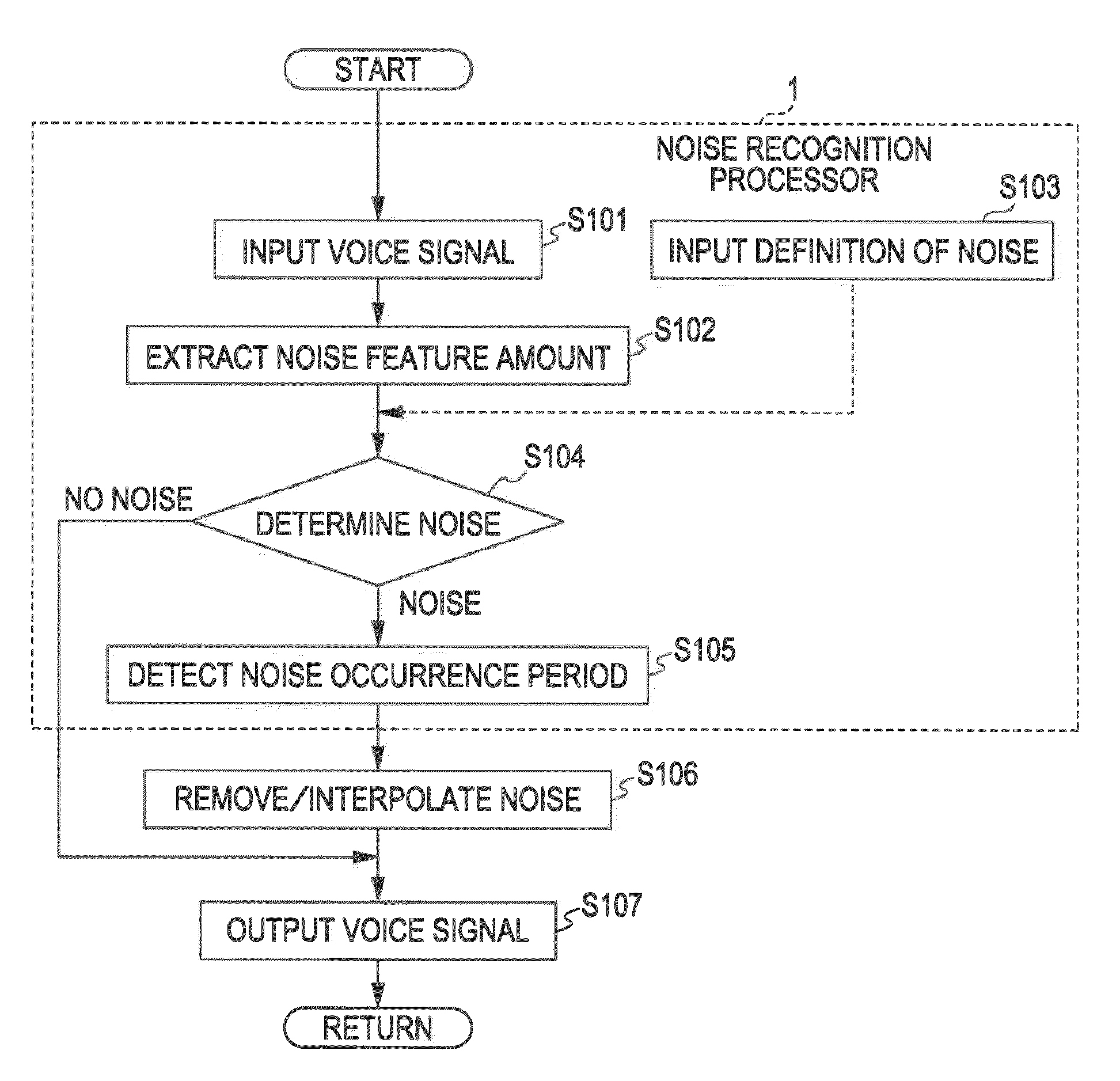
[0193]FIG. 14 is a diagram illustrating a first example of the noise reducing apparatus including the noise recognition processor 1 as the first example or the noise recognition processor 1A as the second example according to the embodiment.

[0194]The noise reducing apparatus shown in FIG. 14 includes a microphone 31, an amplifier 32, a noise removing filter 33, an adder 34, an interpolation signal source generator 35, an interpolation filter 36, a noise recognition processor 37, a noise time generation processor 38, and a switch 39.

[0195]The microphone 31 is included in or connected to the outside of an electronic apparatus mounted in the noise reducing apparatus shown in the drawing. For example, when the electronic apparatus is a video camera, the microphone 31 is disposed so as to receive a recording voice. The microphone 31 receives a removing target noise in this embodiment and a voi...

second example

5. Exemplary Configuration of Noise Reducing Apparatus (Second Example)

[0250]FIG. 15 is a diagram illustrating a second example of the noise reducing apparatus according to this embodiment. In the drawing, the same reference numerals are given to the same elements as those in FIG. 14, and the description is omitted.

[0251]In FIG. 15, a source interpolation signal generator 35A is provided instead of the interpolation signal source generator 35 shown in FIG. 14.

[0252]The source voice signal is input from the amplifier 32 to the interpolation signal source generator 35. The noise recognition information is input from the noise time generation processor 38.

[0253]The interpolation signal source generator 35 in FIG. 14 independently generates the interpolation signal source, that is, the base signal of the interpolation signal. However, the source interpolation signal generator 35A in FIG. 15 generates a base voice signal of the interpolation signal on the basis of the voice signal (input...

third example

6. Exemplary Configuration of Noise Reducing Apparatus (Third Example)

6-1. Exemplary Overall Configuration

[0271]Next, third and fourth examples of the noise reducing apparatus according to this embodiment will be described. In the third and fourth examples, an interpolation signal generating process performed on the basis of a pitch period is applied, as described below.

[0272]FIG. 20 is a diagram illustrating an exemplary configuration of the noise reducing apparatus as the third example according to this embodiment. In the configuration shown in FIG. 20, the interpolation signal generating process performed in the noise reducing apparatus as the second example shown in FIG. 15 is configured on the basis of the pitch period. In FIG. 20, the same reference numerals are given to the same elements as those in FIG. 15, and the description is omitted.

[0273]In the configuration shown in FIG. 20, a pitch calculator 51 is added to the configuration shown in FIG. 15. Here, instead of the sou...


PUM


Abstract

A noise reducing apparatus includes: a voice signal inputting unit inputting an input voice signal; a noise occurrence period detecting unit detecting a noise occurrence period; a noise removing unit removing a noise for the noise occurrence period; a generation source signal acquiring unit acquiring a generation source signal with a time duration corresponding to a time duration corresponding to the noise occurrence period; a pitch calculating unit calculating a pitch of an input voice signal interval; an interval signal setting unit setting interval signals divided in each unit period interval; an interpolation signal generating unit generating an interpolation signal with the time duration corresponding to the noise occurrence period and alternately arranging the interval signal in a forward time direction and the interval signal in a backward time direction; and a combining unit combining the interpolation signal and the input voice signal, from which the noise is removed.

Description

BACKGROUND OF THE INVENTION[0001]1. Field of the Invention[0002]The present invention relates to a noise reducing apparatus and a noise removing (reducing) method capable of reducing a noise contained in a voice signal, for example.[0003]2. Description of the Related Art[0004]An electronic apparatus such as a video camera, a digital camera, a cellular phone, or an IC recorder has a microphone therein. In such an electronic apparatus, a noise, such as a head seek sound or a retract sound of an inner disk driver or the like, a lens drive sound of a lens mechanism, or a click sound or a touch sound of a user operation, may irregularly occur intermittently over time. In such an electronic apparatus, a problem may arise in that a microphone picks up the noise.[0005]In order to solve this problem, Japanese Unexamined Patent Application Publication No. 2008-52772, Japanese Unexamined Patent Application Publication No. 2008-71374, and Japanese Unexamined Patent Application Publication No. 2...

Claims


Application Information

Patent Timeline
Patent Type & Authority Applications(United States)
IPC IPC(8): H04B15/00G10L21/00G10L25/03G10L21/0208G10L21/0224G10L21/0264G10L25/18G10L25/78G10L25/84G10L25/90
CPCG10L21/0208G11B20/24G10L25/90G10L21/0264
Inventor OZAWA, KAZUHIKO
Owner SONY CORP
Why Eureka
Try Eureka