
Apparatus and method for a universal patient controlled medical binder

Inactive Publication Date: 2010-10-14
CRAGO MICHAEL GERARD
View PDF2 Cites 2 Cited by
  • Summary
  • Abstract
  • Description
  • Claims
  • Application Information

AI Technical Summary

Benefits of technology

[0017]In accordance with the present invention, there is provided . . . a universal medical binder that is patient controlled, restoring maximum stability to a specific body part. The device is constructed of a unique material, making it possible for a hook type lock material (Velcro) to be attached on either side. The device has a series of loop rings on the back that allows the material to be directed through the loop rings and then be folded back over itself to adjust the size of the device to accommodate a wide range of body parts. The specially designed loop rings work as a block and tackle system reducing the amount of strength required by the patient to activate the device and maximize support to a specific body part.

Problems solved by technology

During the rehabilitation period there are risks of complications that can result in not only wound morbity but patient mortality.
The expansion of the chest during coughing in a small percentage of patients can lead to sternal dehiscence.
Smaller sizes can be difficult for frail patients to utilize as they have compromised strength after surgery.
The single sided loop material is very flimsy and tends to ride up the back of the patient, changing the location of support.
This device is not dynamic in the respect that there is no way to control the amount of tension applied to a specific body part to accommodate various activities.
This device doesn't provide any controllable support to stabilize a body part, it is strictly utilized by a caregiver to help support an ambulating patient.
This device does not provide circumferential support which is the key factor in reducing potential complications and promoting faster healing in post operative patients.

Method used


Image

  • Apparatus and method for a universal patient controlled medical binder
  • Apparatus and method for a universal patient controlled medical binder
  • Apparatus and method for a universal patient controlled medical binder

Examples


Embodiment Construction

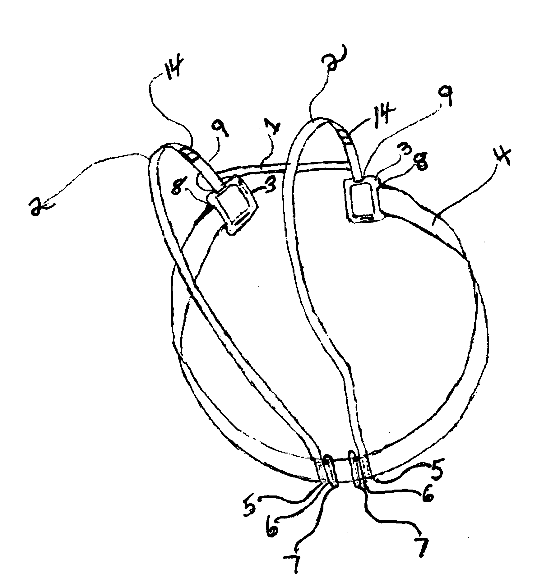
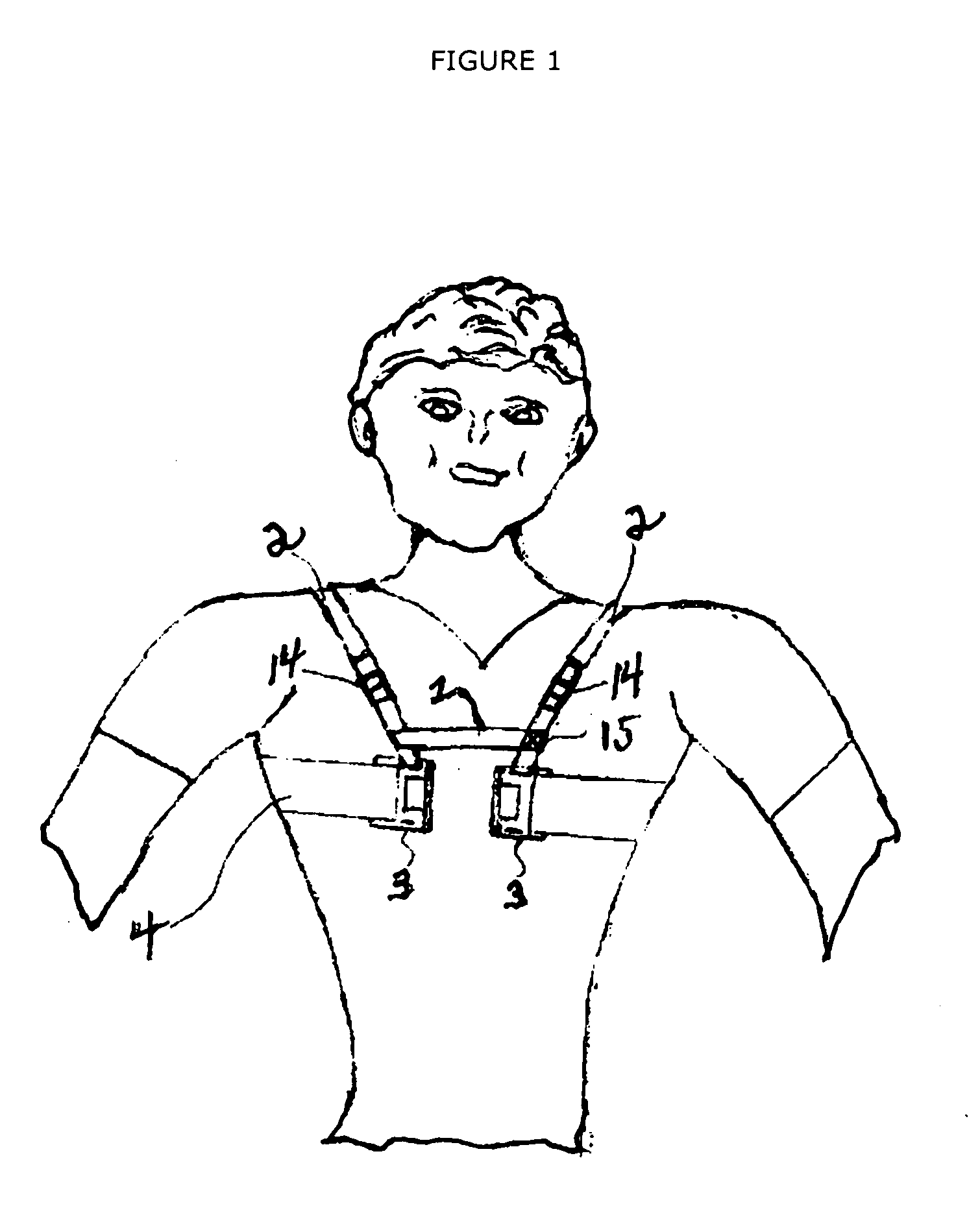
[0033]FIG. 1 is a front perspective view of an embodiment of the medical device of the present invention showing the device on a human body.

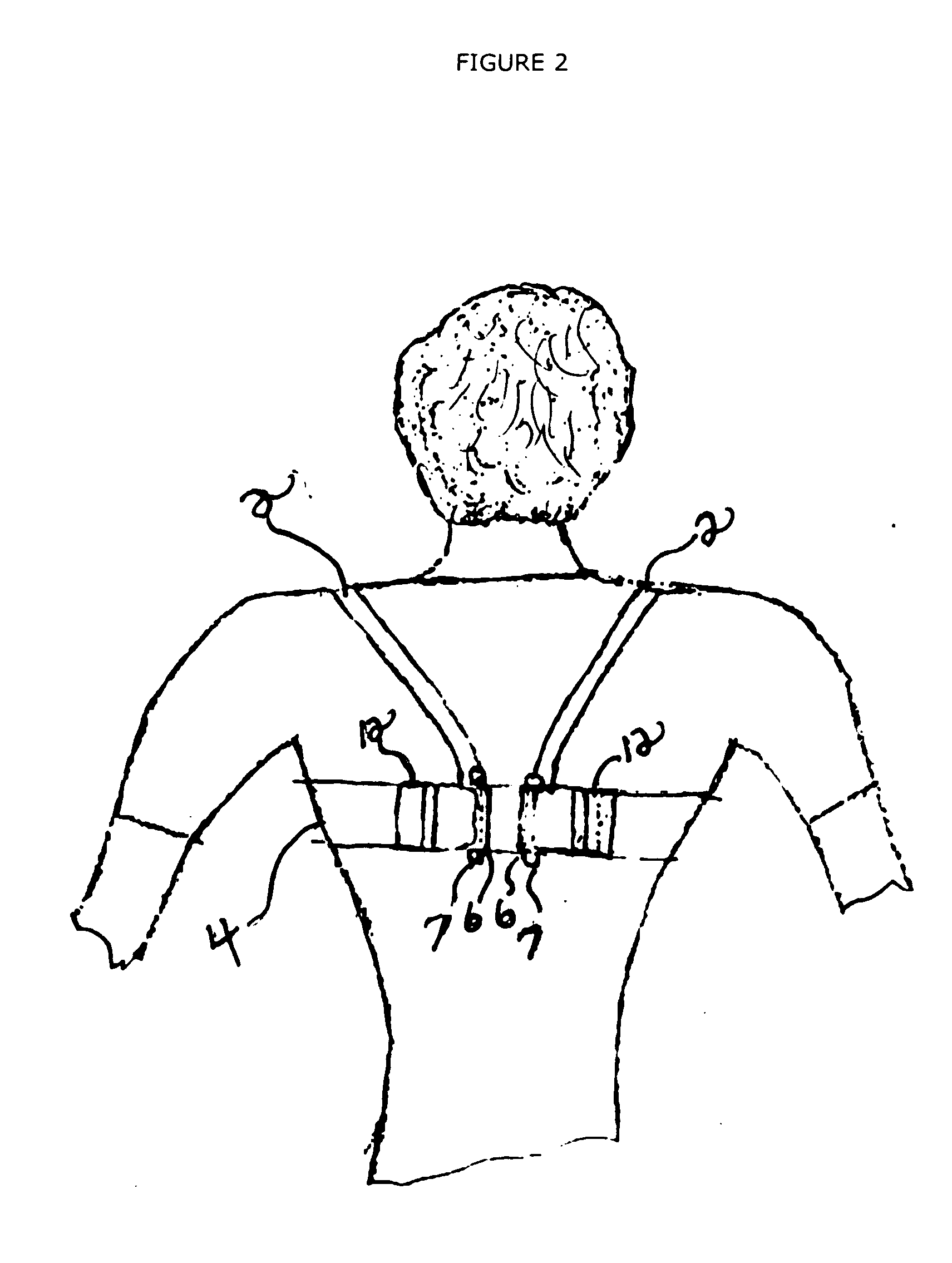
[0034]FIG. 2 is a rear perspective view of an embodiment of the device of the present invention illustrating the position of the device on the mid-back section of the human body.

[0035]FIG. 3 is a front perspective view of an embodiment of the device of the present invention illustrating the device positioned mid-sternum and being activated by a patient.

[0036]FIG. 4 is a rear perspective view of a medical device shown in FIG. 1, adjusted to a full open position accommodating larger body parts.

[0037]FIG. 5 is a rear perspective view of a medical device shown in FIG. 1, adjusted to the medium size accommodating average size body parts.

[0038]FIG. 6 is a rear perspective view of a medical device shown in FIG. 1, adjusted to it's smallest size to accommodate very small body parts.

[0039]FIG. 7 is a top detail view of an universal squeeze handle with va...


PUM


Abstract

A universal medical binder that is patient controlled, restoring maximum stability to a specific body part. The device is constructed of a unique material, making it possible for a hook type lock material (Velcro) to be attached on either side. The binder has a series of loop rings on the back that allows the material to be directed through the loop rings and then be folded back over itself to minimize the size of the device to accommodate a wide range of body parts. The specially designed loop rings act like a block and tackle system reducing the amount of strength required by the patient to activate the device and maximize support to a specific body part.

Description

RELATED APPLICATIONS [0001]The present application is related to U.S. Pat. No. 4,641,642, issued Feb. 10, 1987, for PATIENT ACTIVATED BODY IMMOBILIZER, by williams, included by reference herein.[0002]The present application is related to U.S. Pat. No. 4,273,130, issued Dec. 11, 1981, for CONSTRICTOR, by Simpson, included by reference herein.[0003]The present application is related to U.S. Pat. No. 4,390,014, issued Jun. 28, 1983, for SELF RETAINING RIB BELT, by Forman, included by reference herein.[0004]The present application is related to U.S. Pat. No. 2,900,976, issued Aug. 25, 1959, for MOVING HARNESS, by Kilmer, included by reference herein.[0005]The present application is related to U.S. Pat. No. 5,363,523, issued Mar. 14, 1994, for SURGICAL PILLOW WITH REMOVABLE WEIGHT, by Blackburn, included by reference herein.FIELD OF THE INVENTION [0006]The present invention relates to an adjustable universal medical binder and, more particularly, to a medical device that is patient contr...

Claims


Application Information

Patent Timeline
IPC IPC(8): A61F5/02
CPCA61F5/026
Inventor CRAGO, MICHAEL GERARD
Owner CRAGO MICHAEL GERARD
Learn More