Microneedle roller and stamp adapted to enable the replacement of microneedles

a microneedle roller and roller head technology, applied in the field of microneedle rollers and stamps, can solve the problems of germ infection, difficult removal of microneedles from the roller head for replacement, and low percutaneous or transcutaneous absorption of active ingredients of microneedles, and achieve the effect of inexpensive and sanitarian replacemen

Inactive Publication Date: 2010-10-14
MITI SYST
View PDF1 Cites 38 Cited by
  • Summary
  • Abstract
  • Description
  • Claims
  • Application Information

AI Technical Summary

Benefits of technology

[0008]The present invention has been made in view of the above-mentioned problems occurring in the prior art, and it is an object of the present invention to provide a microneedle roller and a stamp that allow microneedles to be replaced inexpensively and sanitarily.
[0011]According to the microneedle rollers and stamps, when the microneedles are damaged or contaminated, they can be replaced easily and sanitarily, which provides user convenience.

Problems solved by technology

In general, transdermal delivery of a cosmetic agent or a drug is disadvantageous in that since the stratum corneum makes it difficult for the agent and drug to penetrate therethrough, percutaneous or transcutaneous absorption of active ingredients thereof is extremely low.
Such a conventional microneedle roller is configured to include a roller head formed integrally with microneedles and a main body, which makes it difficult to remove the microneedles from the roller head for replacement.
Thus, replacement of the microneedles is not available when in use, which causes a problem of germ infection.
In addition, if the microneedles are damaged or broken, it is required that the entire microneedle roller should be replaced with a new one.

Method used


Image

  • Microneedle roller and stamp adapted to enable the replacement of microneedles
  • Microneedle roller and stamp adapted to enable the replacement of microneedles
  • Microneedle roller and stamp adapted to enable the replacement of microneedles

Examples


first embodiment

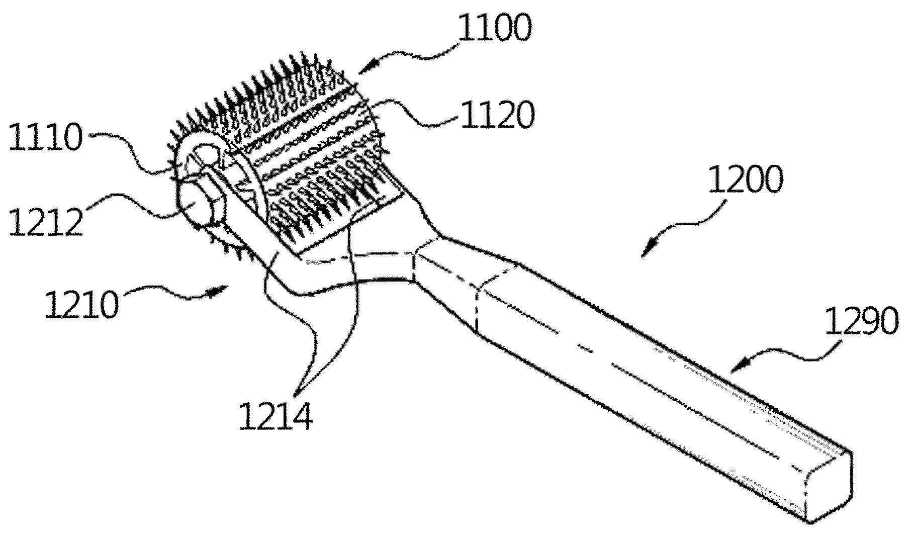
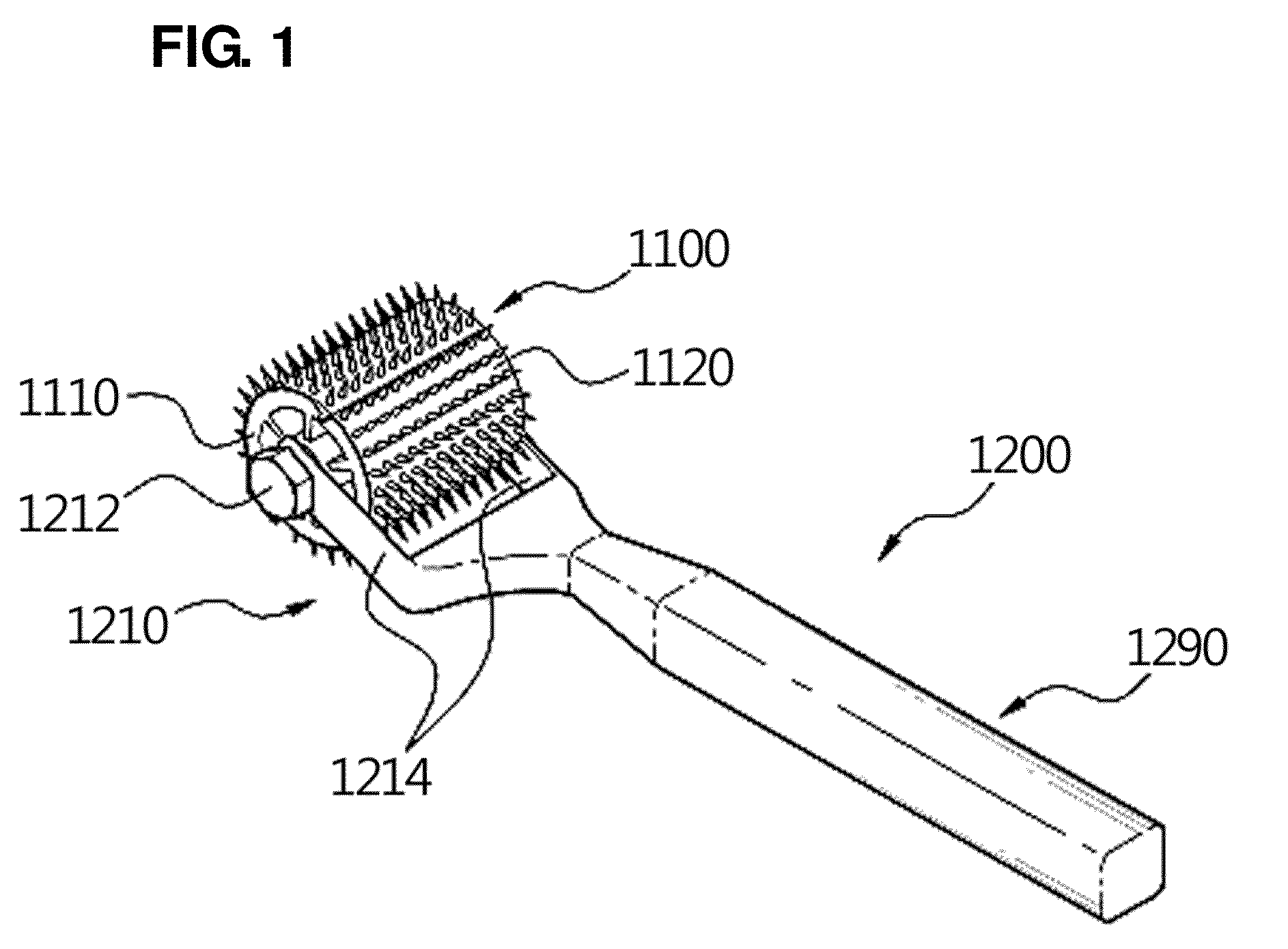
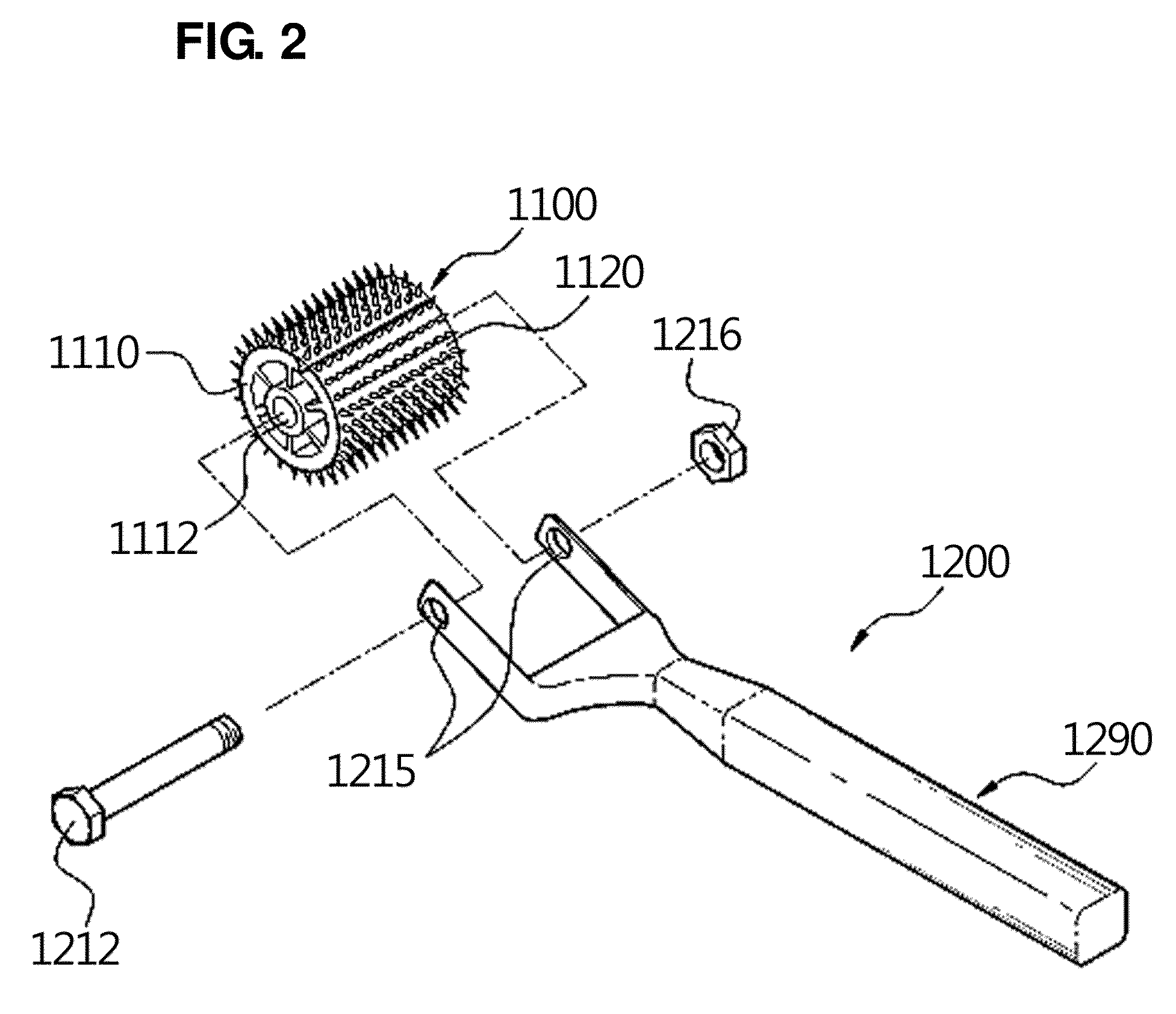
[0029]FIG. 1 is an assembled perspective view illustrating a microneedle-replaceable roller according to the present invention, and FIG. 2 is an exploded perspective view illustrating the microneedle-replaceable roller of FIG. 1.

[0030]Referring to FIGS. 1 and 2, the microneedle-replaceable roller according to the first embodiment of the present invention includes a roller head 1100 and a main body 1200.

[0031]The roller head 1100 includes a cylindrical rotating body 1110 and a microneedle sheet 1120.

[0032]The cylindrical rotating body 1110 has a central hollow portion 1112 formed centrally in the cylindrical rotating body in the direction of a rotational axis thereof, and a microneedle sheet 1120 is wrappingly mounted on the outer circumferential surface of the cylindrical rotating body.

[0033]FIG. 3 is a perspective view illustrating a cylindrical rotating body of a roller head of the microneedle roller adapted to enable the replacement of microneedles shown in FIG. 1.

[0034]Referring...

second embodiment

[0048]FIG. 5 is an exploded perspective view illustrating a microneedle-replaceable roller according to the present invention.

[0049]Since the microneedle-replaceable roller of the second embodiment has the same structure as that of the first embodiment except for its support portion 2210, description of the support portion 2210 will be given while description of the other elements of the structure is omitted.

[0050]The support portion 2210 according to this embodiment includes a clamp arm 2214 having an engagement rod 2212 adapted to penetratingly pass through the hollow portion 1112 formed centrally in the cylindrical rotating body 1110 in the direction of the rotational axis of the cylindrical rotating body 1110, and a fastening member 2216 which is to be press-fittingly engaged with a distal end of the engagement rod 2212 such that the roller head 1100 is interposed between the clamp arm 2214 and the fastening member 2216.

[0051]It will be apparent to those skilled in the art that ...

third embodiment

[0053]FIG. 6 is an exploded perspective view illustrating a microneedle-replaceable roller according to the present invention, FIG. 7 is a perspective view illustrating a cylindrical rotating body of the roller head of the roller of FIG. 6, and FIG. 8 is a bottom perspective view illustrating a microneedle sheet of the roller of FIG. 6.

[0054]Referring to FIG. 6, the roller according to the third embodiment includes a roller head 3100 and a main body 3200.

[0055]The roller head 3100 includes a cylindrical rotating body 3110 and a microneedle sheet 3120.

[0056]The cylindrical rotating body 3110 has a central hollow portion 3112 formed centrally in the cylindrical rotating body in the direction of a rotational axis thereof, and a microneedle sheet 3120 is wrappingly mounted on the outer circumferential surface of the cylindrical rotating body.

[0057]The cylindrical rotating body 3110 has a retaining groove 3114 formed on the outer circumferential surface thereof in a transverse direction ...


PUM


Abstract

A microneedle-replaceable roller and stamp comprises a main body having a handle portion and a microneedle plate or sheet that is detachably mounted to the main body. According to the roller and stamp, inexpensive and sanitary application can be ensured.

Description

CROSS-REFERENCE TO RELATED APPLICATION[0001]This is a continuation of International Application PCT / KR2009 / 001093, with an international filing date of Mar. 5, 2009, which claims the benefit of Korean Application No. 10-2008-0077360 filed Aug. 7, 2008, the entire contents of which are incorporated herein by reference.TECHNICAL FIELD[0002]The present invention relates to a microneedle roller and stamp, and more particularly, to a microneedle roller and stamp having replaceable microneedles.BACKGROUND ART[0003]In general, transdermal delivery of a cosmetic agent or a drug is disadvantageous in that since the stratum corneum makes it difficult for the agent and drug to penetrate therethrough, percutaneous or transcutaneous absorption of active ingredients thereof is extremely low. Particularly, if the active ingredients have a large molecular weight, the absorption becomes further low.[0004]One proposed technique to solve this problem was to drug delivery method using microneedles. Acc...

Claims


Application Information

Patent Timeline
Patent Type & Authority Applications(United States)
IPC IPC(8): A61M5/00
CPCA61M37/0015A61M2037/0046A61M2037/0023A61M5/158A61M37/00
Inventor LEE, SEUNG SEOBSUL, BOO JOONHAN, MAN HEE
Owner MITI SYST
Why Eureka
Try Eureka