Intervertebral implant to immobilize one vertebra relative to another

a technology of intervertebral implants and vertebrae, which is applied in the field of intervertebral implants, can solve the problems of relative risk of implementation, inability to use spinal vertebrae, and insufficient satisfaction of the vertebral fusion obtained, and achieves the effect of convenient introduction

Inactive Publication Date: 2010-10-14
MEDICREA INT SA
View PDF12 Cites 23 Cited by
  • Summary
  • Abstract
  • Description
  • Claims
  • Application Information

AI Technical Summary

Benefits of technology

[0012]The primary objective of the invention is therefore to resolve the drawbacks of the prior art, by providing an implant which can be easil

Problems solved by technology

This technique has the drawbacks of being relatively risky to implement, involving the piercing of holes near the spinal cord, requiring the use of hollow implants with a reduced width, allowing only a small contact surface of the grafts with the vertebrae, and not being usable on spinal vertebrae, for reasons related to anatomy.
This type of implant, largely used in p

Method used


Image

  • Intervertebral implant to immobilize one vertebra relative to another
  • Intervertebral implant to immobilize one vertebra relative to another
  • Intervertebral implant to immobilize one vertebra relative to another

Examples


Embodiment Construction

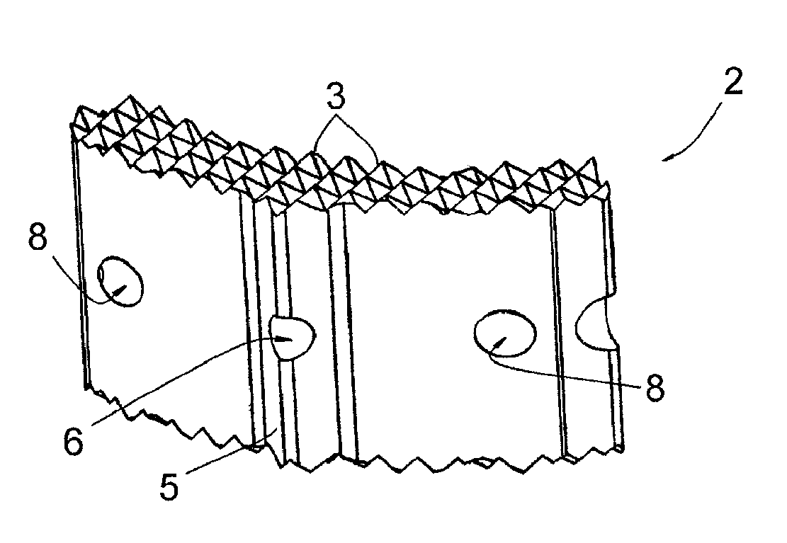
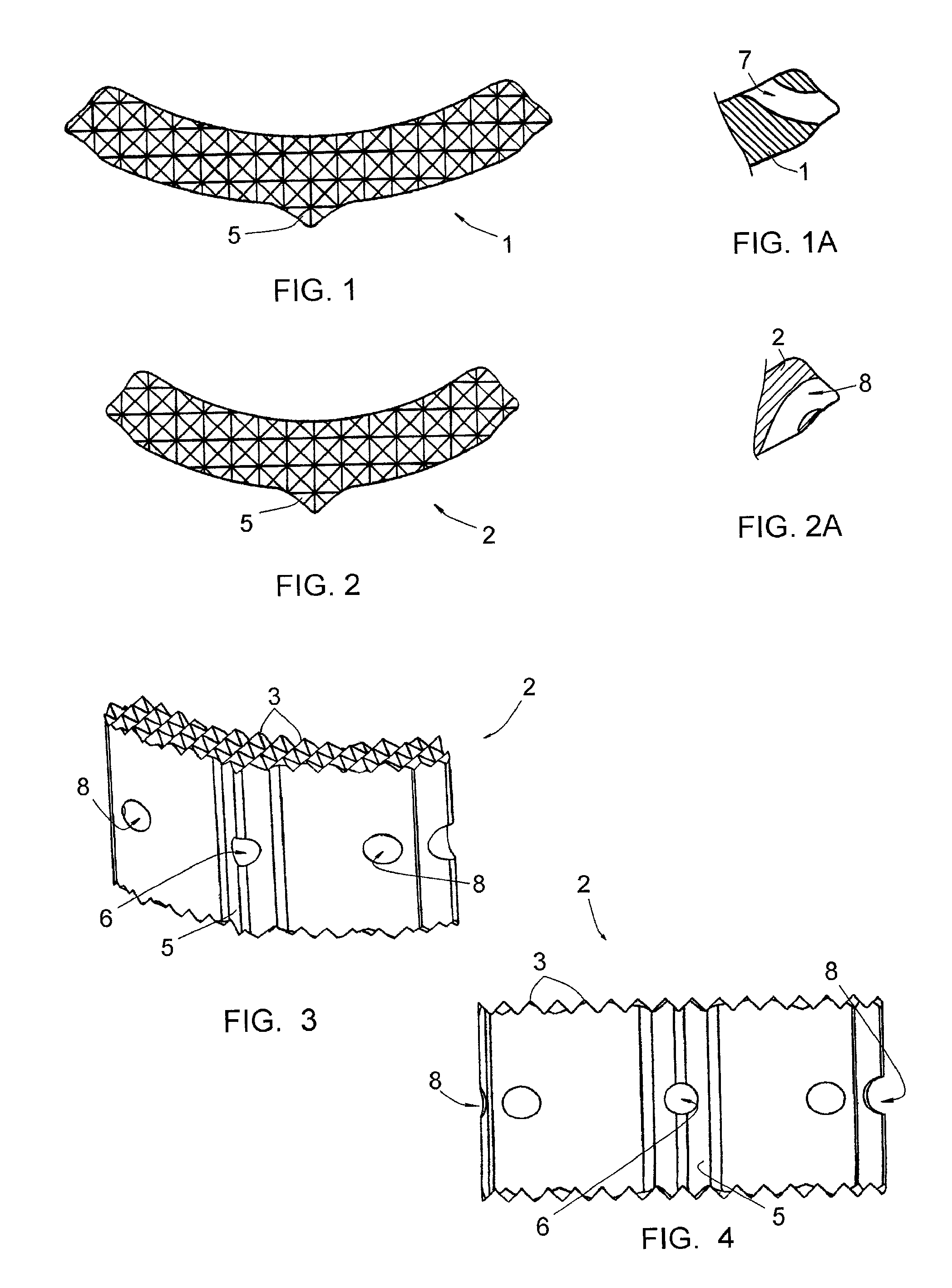
[0064]FIGS. 1 and 2 illustrate two elongated elements 1, 2 jointly making it possible to form an intervertebral implant for immobilization of one vertebra relative to another.

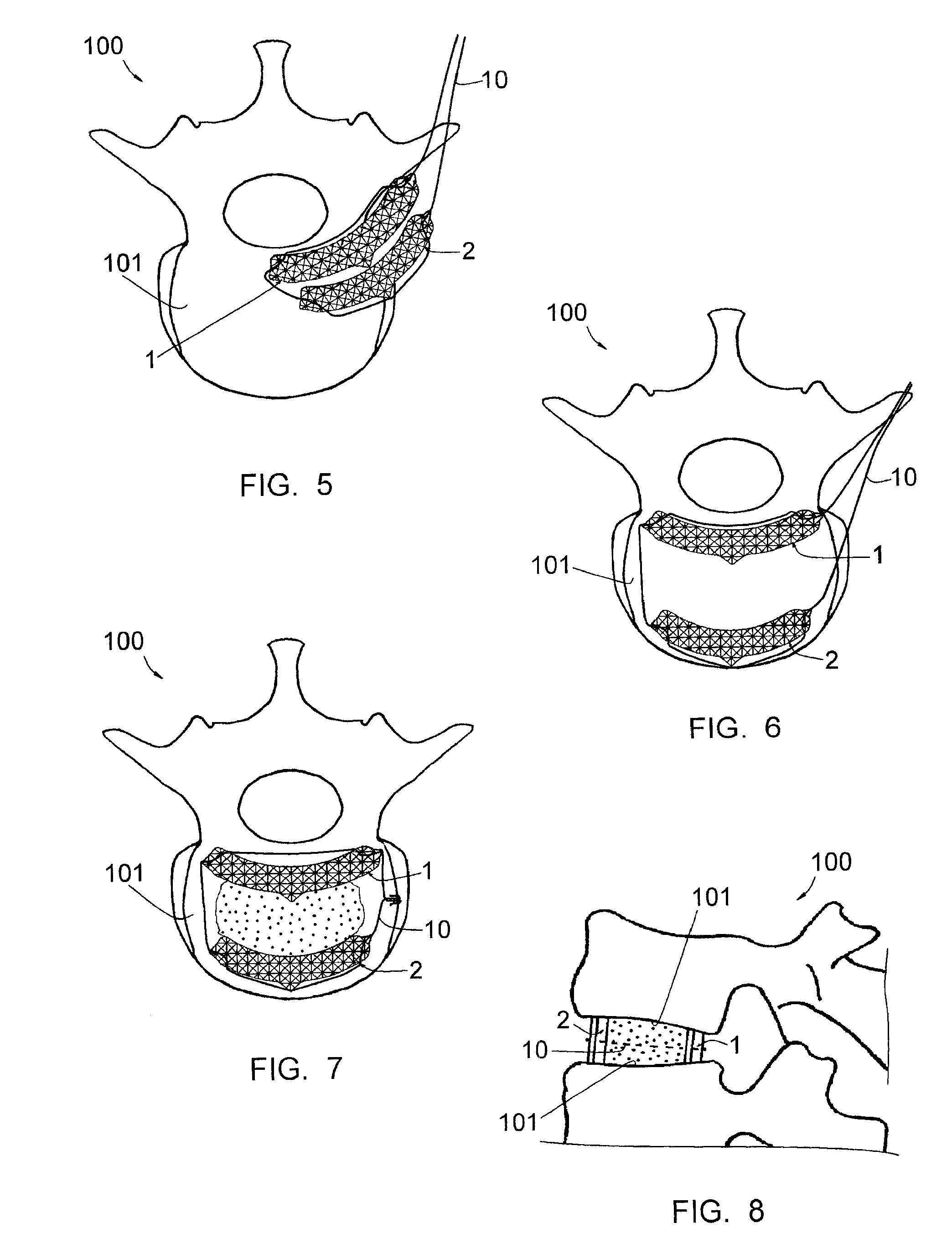
[0065]As shown by FIGS. 6 to 8, the element 1 is intended to be placed from the posterior side of the vertebral plates 101 of two vertebrae 100. It has a length greater than that of the element 2, itself intended to be placed from the anterior side of these plates 101, and has a height smaller than that of said element 2. It appears in FIG. 8 that the respective heights of the elements 1 and 2 are such that these elements make it possible, once placed between the plates 101, to replace the vertebrae 100 in a position of anatomic curvature.

[0066]In reference again to FIGS. 1 to 4, it appears that each element 1, 2 has a curved shape and a reduced width, this width being less than 1 cm. At its edges, each element 1, 2 defines two curved longitudinal surfaces opposite each other, intended to come into contact with...


PUM


Abstract

This implant includes two elongated elements (1, 2) of reduced width, defining, at their edges, two longitudinal surfaces opposite each other. These elements (1, 2) being intended to be positioned between the vertebral plates (101) of the vertebrae, apart from each other, with their longitudinal surfaces in contact with the vertebral plates (101. Elements (1, 2) have curved shapes, having substantially the same curvature from one element (1, 2) to the other, and one of the elements (2) has a length smaller than that of the other element (1), the element (2) with the smaller length being intended to be placed in the anterior position on a vertebral plate (101) while the element (1) with the larger length is intended to be placed in the posterior position on this same vertebral plate (101).

Description

CROSS REFERENCE TO RELATED APPLICATION[0001]This application is a national stage entry of PCT / IB2008 / 054603 filed Nov. 5, 2008, under the International Convention claiming priority over French Application No. 0707754 filed Nov. 5, 2007.FIELD OF THE INVENTION[0002]The present invention concerns an intervertebral implant making it possible to immobilize one vertebra relative to another.[0003]The invention also relates to a surgical procedure with which a vertebra may be immobilized relatively to another.BACKGROUND OF THE INVENTION[0004]It is well known to immobilize two vertebrae relative to each other using an intervertebral implant in a rigid material, forming a cage which defines a housing, this housing being intended to receive one or several bone grafts and / or cancellous bone shavings. The implant makes it possible to reestablish suitable spacing of the vertebrae and to prevent crushing of the graft(s) by the said vertebrae. The vertebrae are immobilized relative to the implant b...

Claims


Application Information

Patent Timeline
IPC IPC(8): A61F2/44A61B17/88
CPCA61F2220/0033A61F2002/4677A61F2220/0083A61F2230/0015A61F2250/0006A61B2017/0256A61F2/4465A61F2/4611A61F2002/30133A61F2002/30331A61F2002/30462A61F2002/30467A61F2002/30538A61F2002/30604A61F2002/30787A61F2002/30841A61F2002/30891A61F2002/448A61F2002/4629A61F2220/0075
Inventor SOURNAC, DENYSRYAN, DAVID
Owner MEDICREA INT SA
Why Eureka
Try Eureka