
Vacuum storage container

Inactive Publication Date: 2010-10-21
DORSEY ROBERT T +1
View PDF9 Cites 34 Cited by
  • Summary
  • Abstract
  • Description
  • Claims
  • Application Information

AI Technical Summary

Benefits of technology

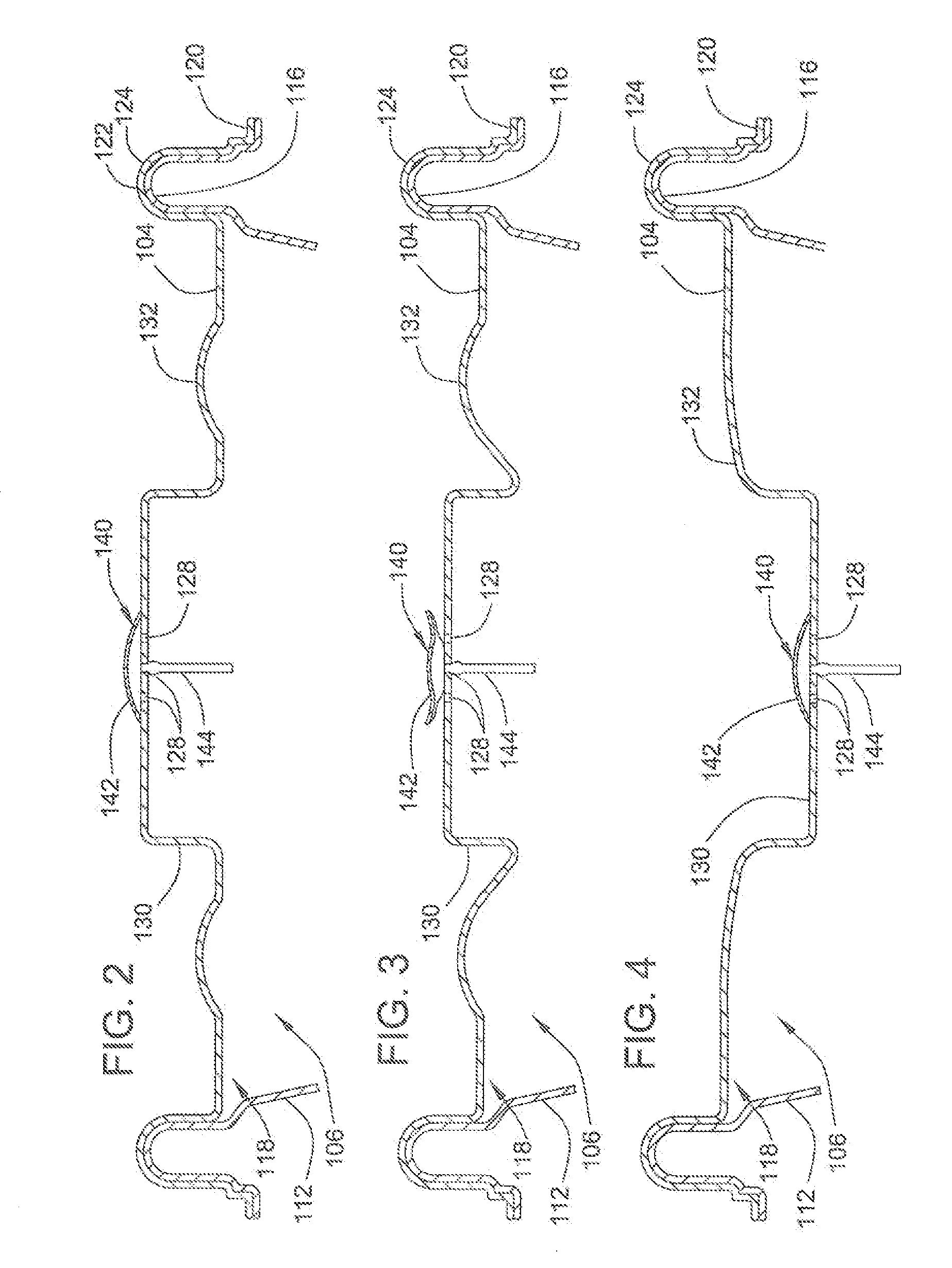
[0004]At least one of the base and / or lid may be made of a flexible or semi-flexible material. For example, in one aspect, the lid can be made comparatively flexible with respect to a more rigid base. Under vacuum conditions, when the air pressure within the storage cavity is reduced with respect to the pressure of the environment surrounding the storage container, the flexible container can collapse or move into the storage cavity. Hence, the storage cavity can have an initial un-evacuated condition with a given initial volume and a subsequent evacuated condition which is less than the initial volume. Additionally, when in the evacuated condition, the storage container can have a reduced head space and smaller overall volume. In other embodiments, the base can be comparatively flexible with respect to the lid or both the lid and the base may demonstrate degrees of flexibility.
[0005]An advantage of the storage container is that it facilitates improving the freshness of food items by retaining those food items in an evacuated state. Another advantage is that, when evacuated, the container has a reduced size and head space for improved storage of the evacuated container. Additionally, the reduced size and / or head space can provide a visual indication to a user about the presence and prolonged maintenance of the evacuated condition of the container. These and other advantages and features of the storage container will be apparent from the following drawings and detailed description of the embodiments.

Problems solved by technology

Under vacuum conditions, when the air pressure within the storage cavity is reduced with respect to the pressure of the environment surrounding the storage container, the flexible container can collapse or move into the storage cavity.

Method used


Image

  • Vacuum storage container
  • Vacuum storage container
  • Vacuum storage container

Examples


Embodiment Construction

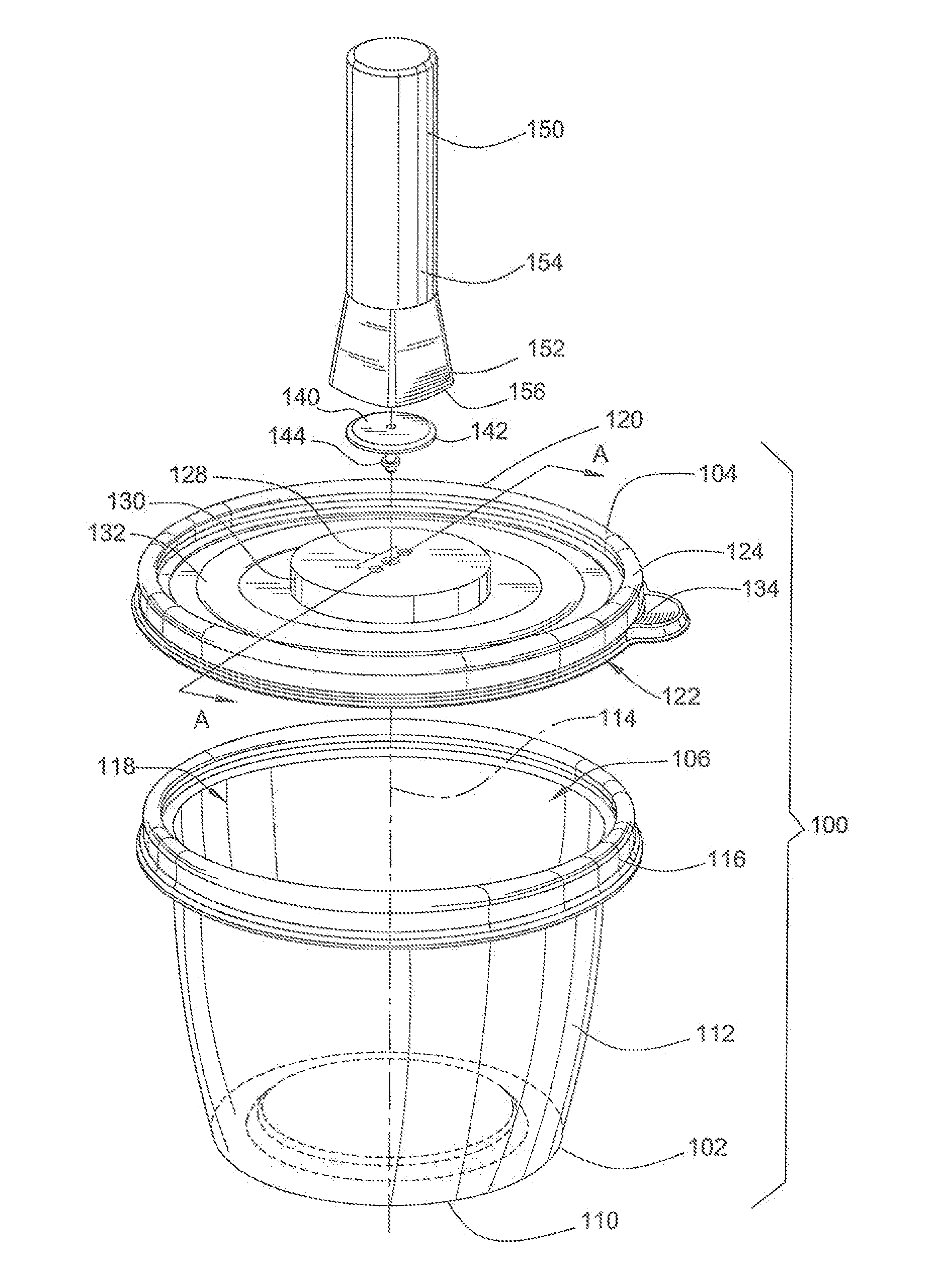
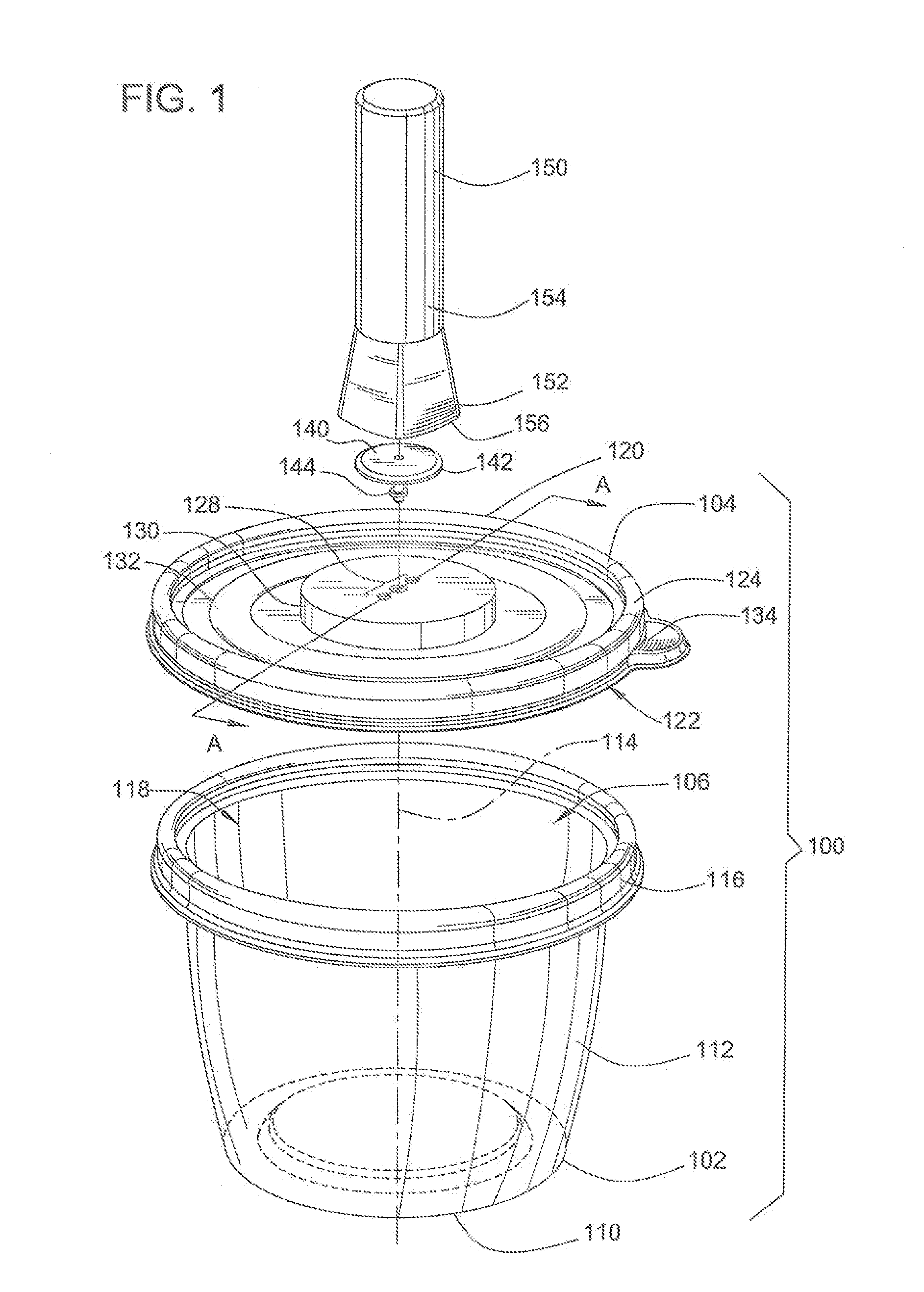
[0030]FIG. 1 illustrates a vacuum storage container 100 that includes a base 102 and a detachable lid 104. To receive items for storage, the base 102 is shaped to delineate a storage cavity 106. In the illustrated embodiment, the base 102 may have a bowl-like shape and may include a generally flat, circular bottom wall 110 and a cylindrical, upward extending sidewall 112 joined to the bottom wall. The bottom wall 110 and the sidewall 112 can generally define a central axis line 114. In some embodiments, to facilitate nested stacking of multiple bases together, the sidewall can inversely taper or angle radially outwards from the axis line 114. The upper edge of the sidewall 112 provides a rim 116 that outlines an opening 118 through which the storage cavity 106 can be accessed. In other embodiments, the storage container can have different shapes including a different number and orientation of the bottom and sidewalls. For example, the storage container can be rectangular and the bas...


PUM


Abstract

A storage container for storing and preserving food items includes a base providing a storage cavity and an attachable lid. To evacuate air from the storage cavity after the base and lid have been attached, the storage container may include a one-way valve element communicating with the storage cavity. The overall storage container can be sufficiently rigid so that it has an initial size and volume when in its un-evacuated condition. During evacuation, the air pressure within the storage cavity is reduced compared to the air pressure of the surrounding environment. This pressure differential can result in a compressive force being applied about the container. At least one of the base or lid can be made relatively flexible so that, when evacuated, the volume of the storage container is reduced.

Description

BACKGROUND[0001]A variety of different containers are available for storing and preserving food items for later consumption. Such containers may be flexible, as in the case of plastic storage bags, or may be rigid, as in the case of plastic storage containers. An advantage of rigid storage containers is that they can maintain their shape and thereby protect the stored food items from being crushed. Another advantage is that rigid containers are usually easily washable and therefore can be reusable. Also, it is desirable that rigid containers be temperature and microwave resistant to allow for heating, cooling and freezing of the stored food items within the container.[0002]To accomplish these advantages, rigid containers are often made as a relatively thick-walled structure of a stiff material such as glass or polycarbonate plastic. Such materials, in addition to being relatively heavy, are also costly. It is also desirable to reduce the quantity of air that may become trapped withi...

Claims


Application Information

Patent Timeline
IPC IPC(8): B65B31/04B65D51/16B65D6/16
CPCB65D43/0218B65D77/20B65D79/005B65D81/2015B65D2543/00092B65D81/2038B65D2543/0037B65D2543/005B65D2543/00537B65D2543/00555B65D2543/00842B65D2543/00296B65D79/0087
Inventor DORSEY, ROBERT T.COONCE, RYAN J.
Owner DORSEY ROBERT T
Learn More