Retention member for perforating guns

a technology of retention member and perforating gun, which is applied in the direction of device material selection, instruments, borehole/well accessories, etc., can solve the problems of reducing the size of the retention member, limiting movement, and affecting the effect of energy coupling

Active Publication Date: 2010-10-21
OWEN OIL TOOLS
View PDF39 Cites 14 Cited by
  • Summary
  • Abstract
  • Description
  • Claims
  • Application Information

AI Technical Summary

Benefits of technology

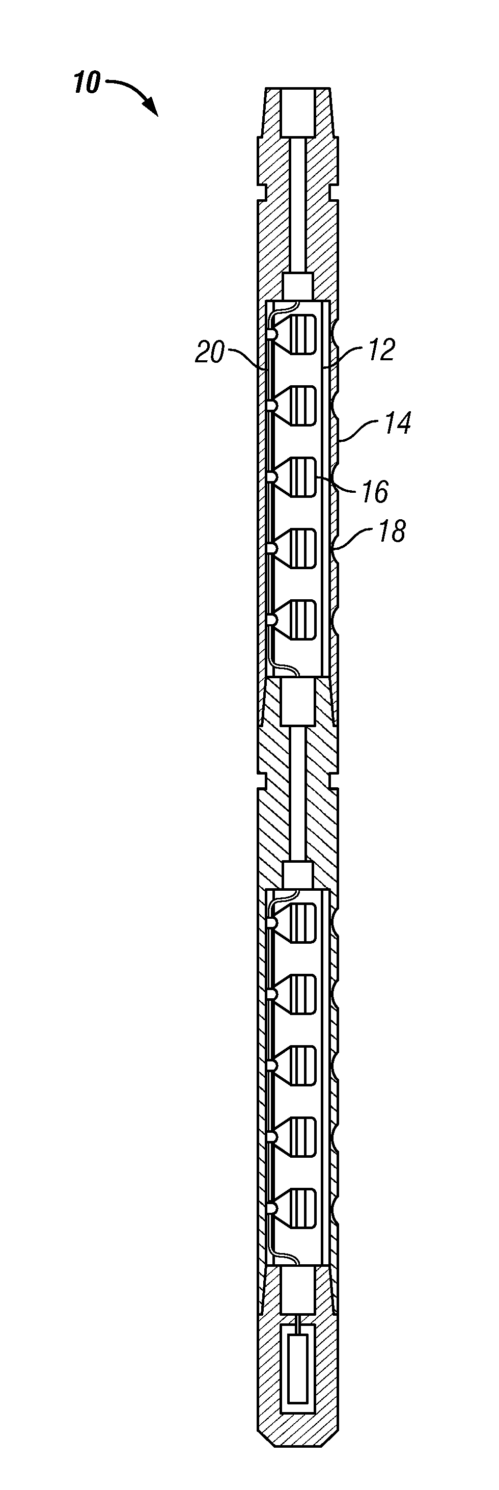
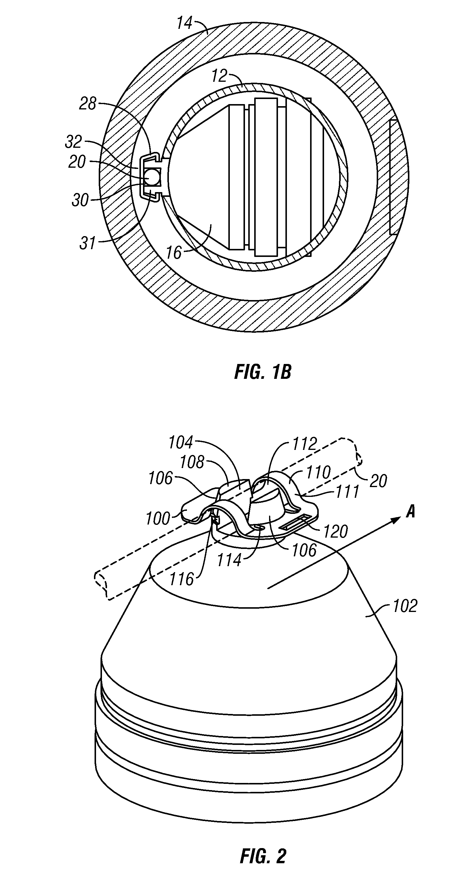
[0008]In some aspects, the present invention provides a perforating gun for perforating a wellbore that has enhanced energetic couplings between the detonator cord and the shaped charges. In one embodiment, the gun includes a charge tube disposed in a carrier tube and shaped charges fixed in the charge tube. Each shaped charge has a body or casing on which is formed a radially outward pointing, substantially cylindrical post. The post has a slot that receives a detonator cord. To ensure that the detonator cord remains energetically coupled to the shaped charge, a retention member installed on the post captures the detonator cord and compresses the cord against the post.
[0009]In some embodiments, only a minor portion of the retention member in contact with the detonator cord extends radially beyond the radially outermost portion of each post. In other words, a major portion of the retention member is radially recessed relative to the radially outermost portion of the post. As used herein, “a major portion” means at least slightly more than half, and in some embodiments significantly more than half. In other embodiments, substantially all of the retention member lies radially flush with or is radially recessed relative to the radially outermost portion of each post. When the charge tube is inserted into the carrier tube during installation, a significantly smaller portion of the retention member, in comparison with conventional means, is likely to undesirably contact either an edge or the interior of the carrier tube. Thus, it is less likely that the retention member will in some way strike the carrier tube as a result of mishandling. Because the retention member is therefore less likely to be damaged or dislodged during such mishandling, there is a correspondingly greater likelihood that the energetic coupling between the detonator cord and the shaped charges will remain intact during assembly and subsequent deployment, increasing the likelihood of a successful perforating operation.

Problems solved by technology

When the charge tube is inserted into the carrier tube during installation, a significantly smaller portion of the retention member, in comparison with conventional means, is likely to undesirably contact either an edge or the interior of the carrier tube.
Such a portion can restrict movement by bumping up against or otherwise interferingly engaging with a post.
As the post enters the central opening, the locking tabs interferingly engage the outer surfaces of the post and deform.

Method used


Image

  • Retention member for perforating guns
  • Retention member for perforating guns
  • Retention member for perforating guns

Examples


Embodiment Construction

[0020]The present invention relates to devices and methods for facilitating the assembly and enhancing the reliability of wellbore perforating tools. The present invention is susceptible to embodiments of different forms. There are shown in the drawings, and herein will be described in detail, specific embodiments of the present invention with the understanding that the present disclosure is to be considered an exemplification of the principles of the invention, and is not intended to limit the invention to that illustrated and described herein.

[0021]Referring now to FIGS. 2 and 3, there is shown one embodiment of a retention member 100 that energetically couples a detonator cord 20 to a shaped charge 102. The detonator cord 20 and shaped charge 102 are generally similar to that already described in connection with FIG. 1A. Merely for convenience, the retention member 100 will be hereafter referred to as a “clip.” However, it should be understood that no particular shape, dimension ...


PUM

PropertyMeasurementUnit
pressureaaaaaaaaaa
shapeaaaaaaaaaa
radial movementaaaaaaaaaa

Abstract

A perforating gun includes a charge tube having shaped charges affixed thereto. Each shaped charge includes a radially outward pointing post adapted to receive a detonator cord. A retention member installed on the post provides a compressive force that energetically couples the detonator cord to the post. The radially outermost portion of the retention member is radially flush with or radially recessed relative to the radially outermost portion of each post. In one embodiment, the retention member has a rounded medial portion, a central opening and a pair of locking tabs that point radially inward to the central opening. Each post may include a slot for receiving the detonator cord and a circumferential groove that is adapted to receive the locking tabs.

Description

CROSS-REFERENCE TO RELATED APPLICATIONS[0001]This application claims priority from U.S. Provisional Patent application Ser. No. 60 / 811,281 filed Jun. 6, 2006.BACKGROUND OF THE INVENTION[0002]1. Field of the Invention[0003]The present invention relates to devices and methods for energetically coupling a detonator cord to one or more shaped charges.[0004]2. Description of the Related Art[0005]Hydrocarbons, such as oil and gas, are produced from cased wellbores intersecting one or more hydrocarbon reservoirs in a formation. These hydrocarbons flow into the wellbore through perforations in the cased wellbore. Perforations are usually made using a perforating gun loaded with shaped charges. The gun is lowered into the wellbore on electric wireline, slickline, tubing, coiled tubing, or other conveyance device until it is adjacent to the hydrocarbon producing formation. Thereafter, a surface signal actuates a firing head associated with the perforating gun, which then detonates the shaped ...

Claims


Application Information

Patent Timeline
Patent Type & Authority Applications(United States)
IPC IPC(8): E21B43/117C06C5/06B23P11/00
CPCG08B13/2437G08B13/2442Y10T428/239H01L41/20Y10T29/49826H01F10/131H10N35/85E21B43/117F42D1/043
Inventor LAGRANGE, TIMOTHY EDWARDANDRICH, LYLE W.DAY, CORY D.PRATT, DAN W.
Owner OWEN OIL TOOLS
Why Eureka
Try Eureka