Magnetising portion for a magnetic separation device

a magnetic separation device and magnetising portion technology, applied in the direction of magnetic separation, separation process, filtration separation, etc., can solve the problems of limited fringe magnetic field strength, weakening of affecting the strength of the fringe magnetic field

Active Publication Date: 2010-10-21
LIFE TECH AS
View PDF39 Cites 27 Cited by
  • Summary
  • Abstract
  • Description
  • Claims
  • Application Information

AI Technical Summary

Benefits of technology

[0008]A first aspect of the present disclosure relates to a magnetising portion for providing a high-gradient magnetic field in a magnetic separation device. The magnetising portion comprises at least one magnetic assembly. The at least one magnetic assembly comprises:

Problems solved by technology

It has been found that the strength and gradient of the fringe magnetic field is compromised as a result of placing magnets in contact with one another.
The strength of the fringe magnetic field is limited because the return flux travels directly through the contacting adjacent magnets to the opposite poles rather than travelling outwardly around the periphery of the magnets towards the opposite poles of adjacent magnets.
Since the strength of the fringe field is limited, the variation in field strength between the high magnetic field density regions and low magnetic field density regions of the fringe field is restricted.
The performance of the magnetic material is compromised as a result of placing the magnets in contact with one another.
For example, the magnetic material may not be able to isolate the smallest micrometre sized particles and will be unsuitable for isolating nanometre sized particles.
The efficiency and accuracy of the separation process will also be restricted.
However, the spacers have very little effect on the gradient of the fringe field because the fringe field is already so weak.
Since the fringe magnetic field is poor the efficiency and accuracy of the separation process is compromised.
More particularly, the magnet arrangement will be unsuitable for isolating smaller (nanometre sized) magnetically labelled particles.
Nevertheless, the field strength and gradient of the fringe magnetic field acting within the receiving space is still restricted because significant magnetic flux continues to extend through the top and bottom pole faces of the ring magnet arrangement rather than within the receiving space.
Moreover, the performance of the magnet arrangement is not constant along the longitudinal axis of the receiving space.
As a direct consequence, the performance of the magnet arrangement is not consistent along the longitudinal axis of the receiving space the efficiency and accuracy of the separating process is compromised.

Method used


Image

  • Magnetising portion for a magnetic separation device
  • Magnetising portion for a magnetic separation device
  • Magnetising portion for a magnetic separation device

Examples


first embodiment

[0096 of the Magnetising Portion

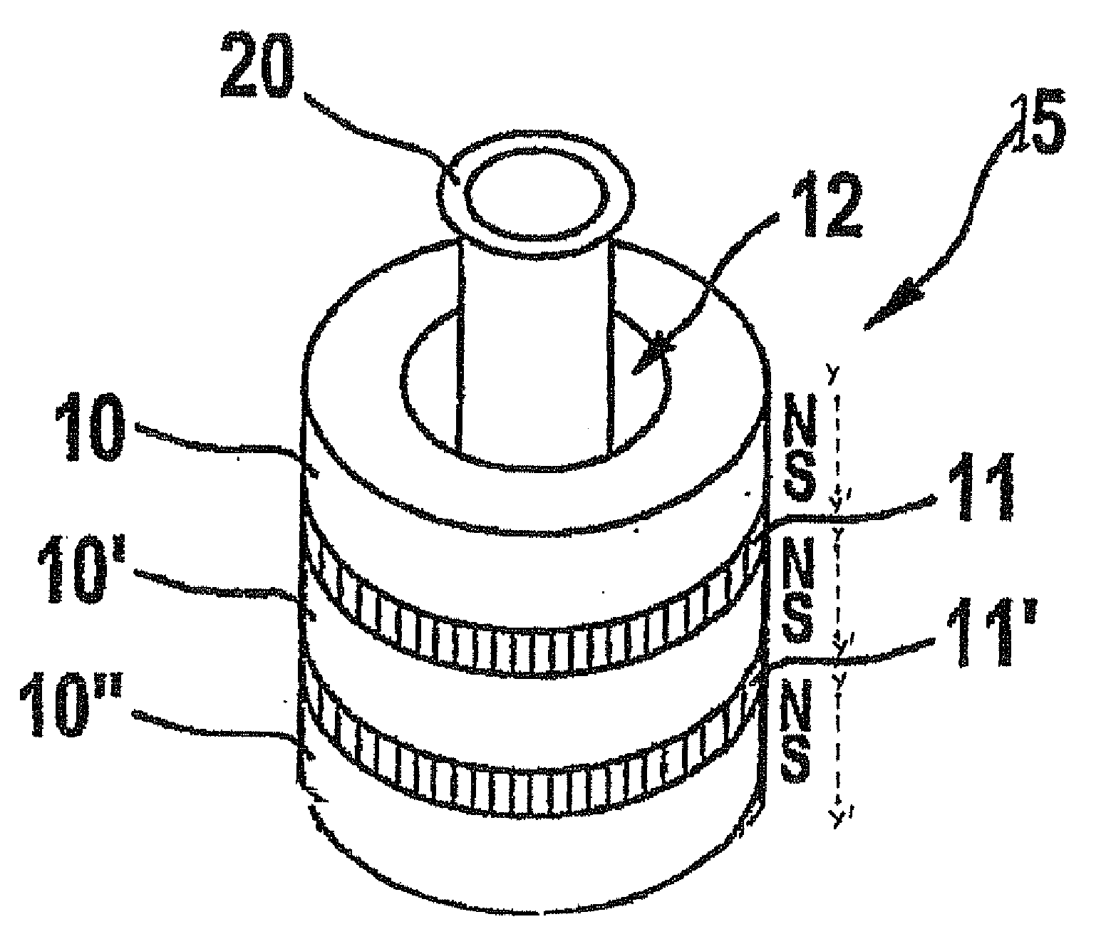
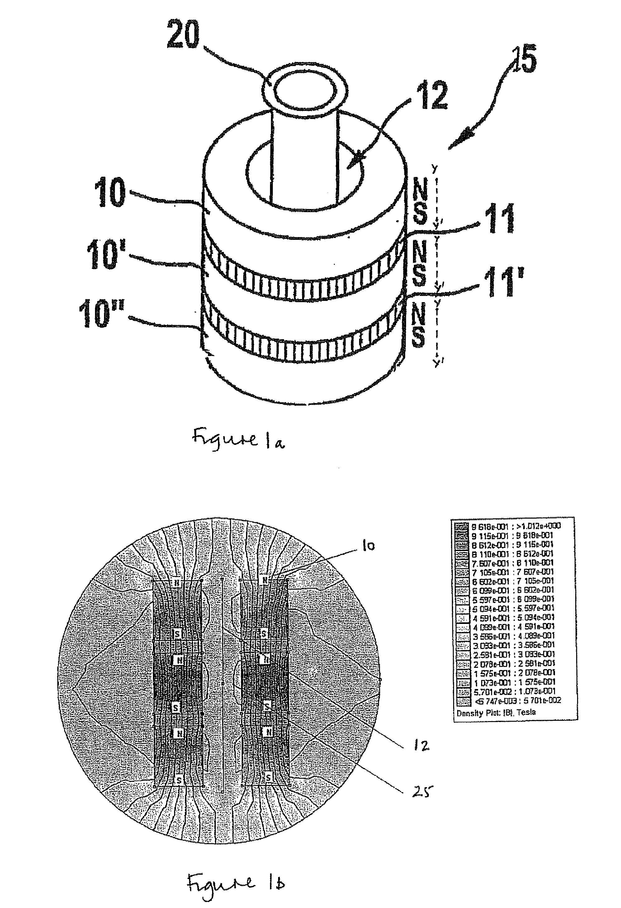
[0097]FIG. 3 depicts an embodiment of the magnetising portion (3) in its simplest form. The magnetising portion (3) comprises a single magnetic assembly with two magnets (M1, M2). The magnets are stacked substantially vertically, one above the other. The magnets are stacked such that the axes (Y-Y′) of each magnet extend substantially horizontally. The two magnets (M1, M2) are arranged such that the north and south poles of adjacent magnets are arrange alternately. The magnets (M1, M2) are bar shaped magnets with flat pole end faces (FEF). An aluminium spacing plate (SP) is arranged between the adjacent magnets; between magnets M1 and M2. The magnetic assembly has cuboid-like shape with two side walls (100, 101), two end faces (102,103), an upper surface (104) and a lower surface (105). End face 102 has a first alternating multipole surface with a NS configuration. End face 103 has a second alternating multipole surface with a SN configuration. The ma...

second embodiment

[0099 of the Magnetising Portion

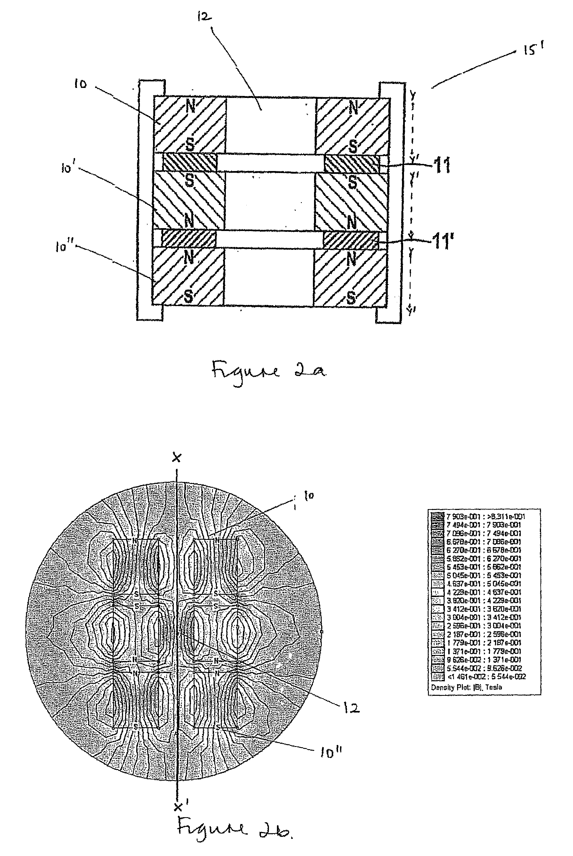
[0100]FIG. 4a depicts a second embodiment of the magnetising portion (3) comprising two magnetic assemblies (3ma, 3mb). The magnetic assemblies are mounted in parallel relation. A central region, void or space is formed between the magnetic assemblies. The void is shaped such that it is suitable for receiving a sample vessel. The centre line, or central longitudinal axis of the magnetising portion (3) is marked X-X′. The central longitudinal axis is the furthest point within the central region from a magnetic assembly and therefore the most difficult area to influence. The first magnetic assembly (3ma) comprises three magnets (M1a-M3a). The magnets of the first magnetic assembly (3ma) are stacked vertically such that the alternating multipole surface facing the second magnetic assembly (3mb) has a NSN configuration. The second magnetic assembly (3mb) also comprises three magnets (M1b-M3b). The magnets of the second magnetic assembly (3mb) are stacked ...

third embodiment

[0104 of the Magnetising Portion

[0105]FIGS. 5a and 5b depict a third embodiment of the magnetising portion (3) comprising a plurality of magnetic assemblies (3ma-3mf) arranged in a substantially radial or circumferential configuration. The magnetic assemblies (3ma-3mf) are arranged in a substantially circumferential array about a magnetic assembly mounting portion (MP).

[0106]Each magnetic assembly comprises two magnets, a first magnet (M1) and a second magnet (M2). The magnets (M1, M2) are stacked vertically in an alternating multipole configuration. An aluminium spacing plate (SP) is arranged between the adjacent magnets. Each magnetic assembly has a first alternating multipole surface with a SN configuration and a second alternating multipole surface with a NS configuration. However, the magnetic field of the second alternating multipole surface is restricted by the magnetic assembly mounting portion (MP). The magnetising portion is configured such that, in use, the first alternat...


PUM

PropertyMeasurementUnit
volumeaaaaaaaaaa
diameteraaaaaaaaaa
volumesaaaaaaaaaa

Abstract

The present disclosure relates to a magnetising portion for providing a high-gradient magnetic field in a magnetic separation device. The magnetising portion comprises at least one magnetic assembly. The at least one magnetic assembly comprises: a plurality of magnets whereby each magnet has a north pole, south pole and a magnet axis extending between the north and south poles, and the plurality of magnets are arranged one above the other in a direction at least substantially perpendicular to the axis of each magnet in such a manner that the north and south poles of adjacent magnets are arranged alternately and a space is provide between adjacent magnets; and at least one non-magnetic spacing means arranged in the space between adjacent magnets. The present disclosure also relates to magnetic separation devices comprising at least one of the said magnetising portions and to a method of isolating magnetically labelled particles using the magnetic separation devices.

Description

FIELD OF DISCLOSURE[0001]This disclosure relates to a magnetising portion suitable for a magnetic separation device. The magnetising portion provides a high-gradient magnetic field that can attract and separate magnetically labelled particles from a non-magnetic medium in which they are contained. The disclosure also relates to a magnetic separation device for isolating magnetically labelled particles, the device comprising the said magnetising portion.BACKGROUND[0002]The use of a high-gradient magnetic field to attract and separate magnetically labelled particles from a fluid in which they are suspended is well known. Moreover, magnetic separation devices are used in a variety of industries including pharmaceutical, medical, agricultural, scientific and engineering fields. For example in biotechnology, a high-gradient magnetic field may be used to separate magnetically labelled bone marrow cells from a blood sample.[0003]A high-gradient magnetic field is conventionally created by c...

Claims


Application Information

Patent Timeline
Patent Type & Authority Applications(United States)
IPC IPC(8): B03C1/031
CPCB03C1/288B03C1/0332B03C2201/18B03C2201/22B03C2201/26B01L9/06
Inventor ELLIS, DARRENHILDISCH, TINE BORGENMUNDY, JEZRAGNHILDSTVEIT, ERLENDTOFTEN, RICHARD JOHANZGONC, KORNELIJAKARLSON, MALINBREDE, GAUTENOKLEBY, LARS
Owner LIFE TECH AS
Why Eureka
Try Eureka