Direct current motor
a direct current motor and motor shaft technology, applied in the direction of dynamo-electric components, ac commutators, dynamo-electric machines, etc., can solve the problems of increasing torque pulsation, magnetic imbalance, and affecting the operation of the motor, so as to reduce vibration and noise.
- Summary
- Abstract
- Description
- Claims
- Application Information
AI Technical Summary
Benefits of technology
Problems solved by technology
Method used
Image
Examples
first embodiment
[0040]the present invention will now be described with reference to FIGS. 1 to 6.
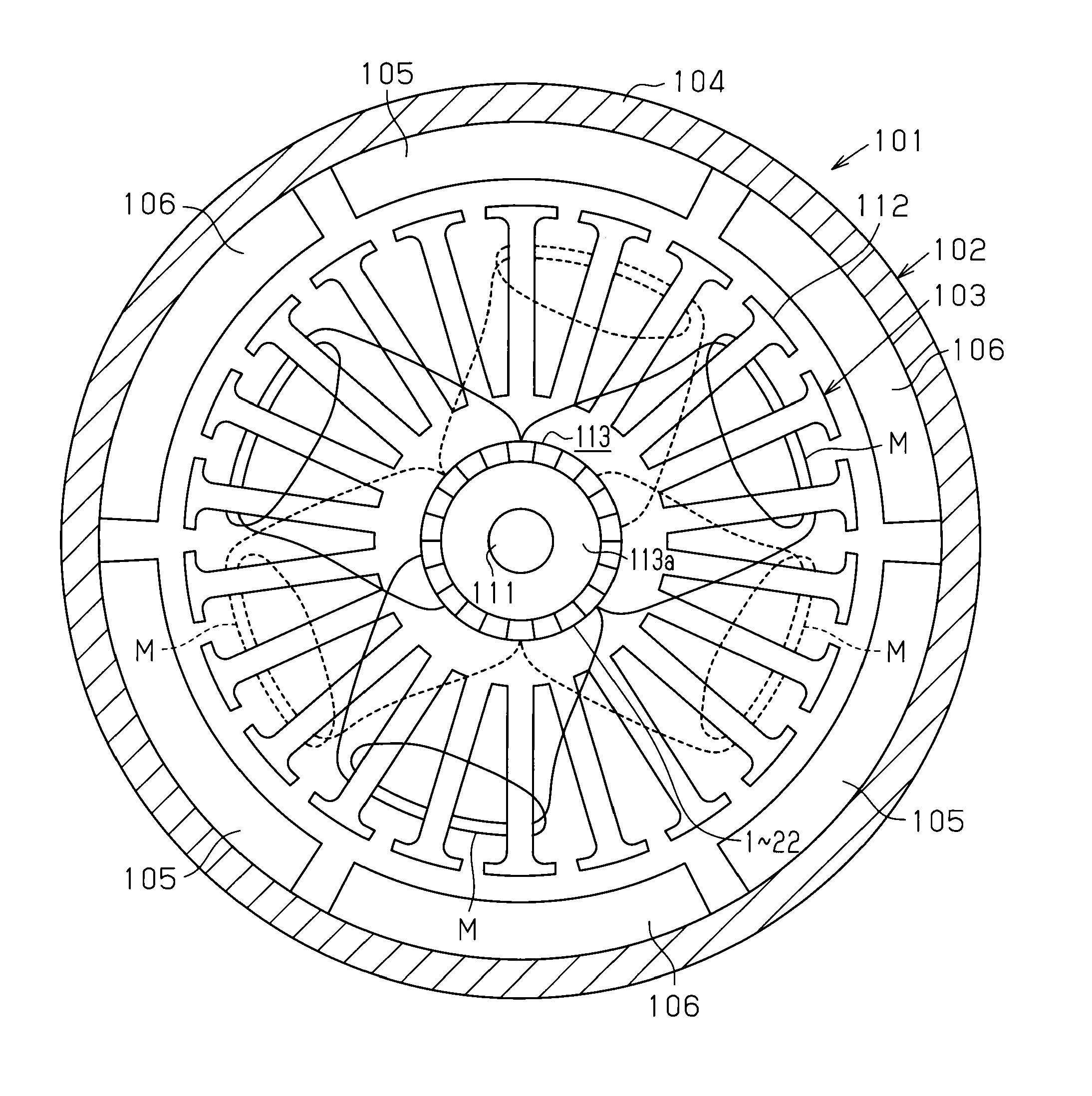
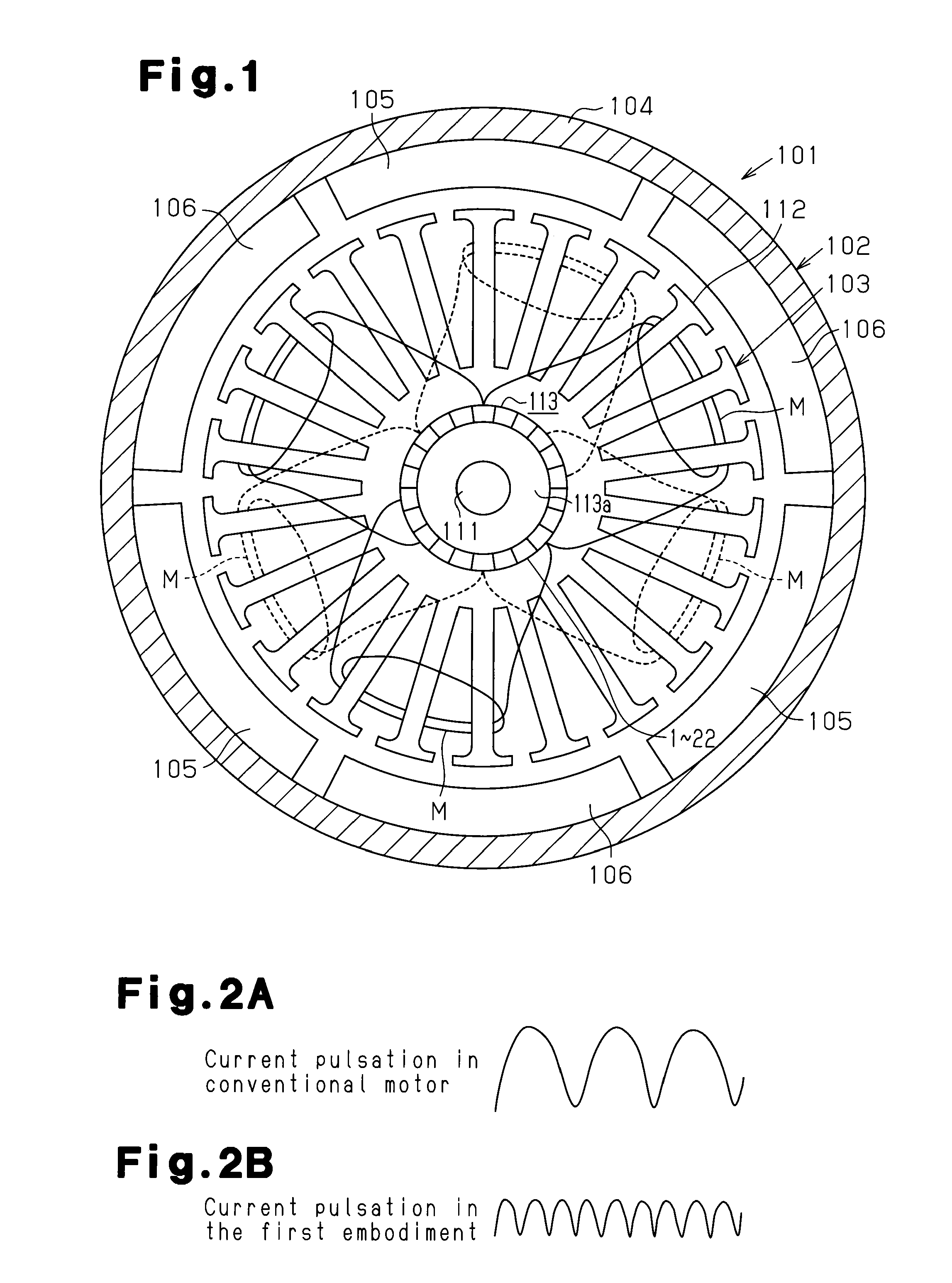
[0041]A direct current motor 101 according to the present embodiment is used for an electric power steering system, and has a stator 102 and an armature (rotor) 103 as shown in FIG. 1. The stator 102 includes a yoke housing 104 and six magnets 105, 106. The yoke housing 104 is substantially cylindrical and servers as a yoke. The magnets 105, 106 are arranged on and fixed to the inner circumferential surface of the yoke housing 104, while being arranged along the circumferential direction at equal angular intervals (60°).
[0042]As shown in FIG. 1, the armature 103 includes a rotary shaft 111, an armature core 112, which is secured to the rotary shaft 111, and a commutator 113, which is secured to the rotary shaft 111. The rotary shaft 111 is rotatably supported by the stator 102. In this state, the armature core 112 is arranged in such manner as to face the magnets 105, 106 in a radial direction and to be...
seventh embodiment
[0137]the present invention will now be described with reference to FIGS. 21 and 22. In the seventh embodiment, like or the same reference numerals are given to those components that are like or the same as the corresponding components of the first embodiment, and detailed explanations thereof are partly omitted.
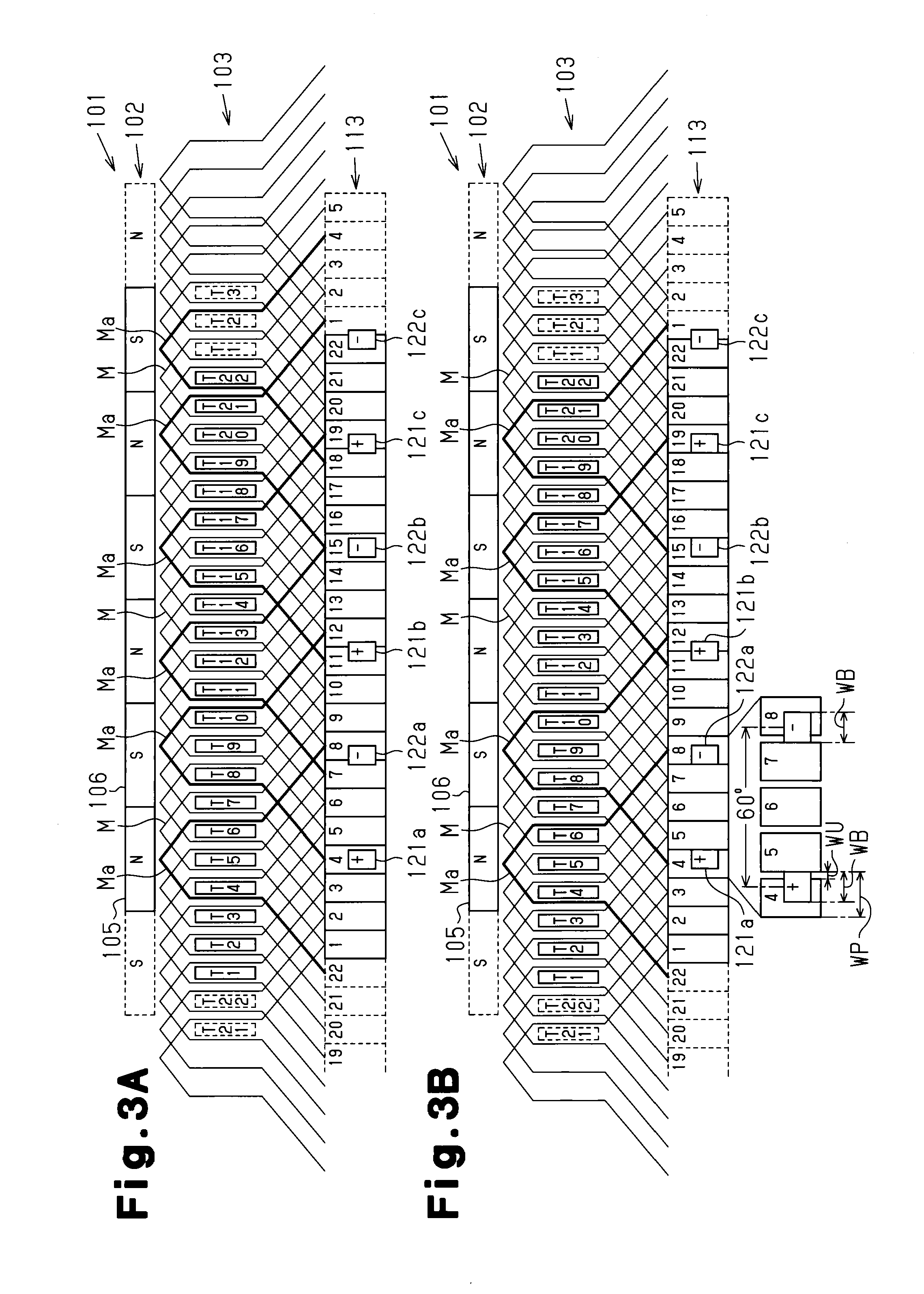
[0138]The coils M of the present embodiment have a different configuration from the coils M of the first embodiment, which are wound by duplex wave winding (for example, see FIG. 3). Specifically, as shown in FIGS. 21 and 22, each pair of coils M that are spaced apart by 180° in the circumferential direction are connected to common ones of the segments 1 to 22. The coils M of the present embodiment are connected such that current is supplied thereto at the same timing at which the coils M wound by duplex wave winding receive current. Specifically, in the present embodiment, each pair of coils M that are spaced apart by 180° in the circumferential direction are connected in s...
eighth embodiment
[0148]the present invention will now be described with reference to FIGS. 23 and 24. In the eight embodiment, like or the same reference numerals are given to those components that are like or the same as the corresponding components of the first embodiment, and detailed explanations thereof are partly omitted.
[0149]The coils M of the present embodiment have a different configuration from the coils M of the first embodiment, which are wound by duplex wave winding (for example, see FIG. 3). Specifically, as shown in FIGS. 23 and 24, each pair of coils M that are spaced apart by 180° in the circumferential direction are connected to common ones of the segments 1 to 22. The coils M of the present embodiment are connected such that current is supplied thereto at the same timing at which the coils M wound by duplex wave winding receive current. Specifically, in the present embodiment, each pair of coils M that are spaced apart by 180° in the circumferential direction are connected in ser...
PUM
 Abstract
Description
Claims
Application Information
 - R&D
- Intellectual Property
- Life Sciences
- Materials
- Tech Scout
- Unparalleled Data Quality
- Higher Quality Content
- 60% Fewer Hallucinations
Browse by: Latest US Patents, China's latest patents, Technical Efficacy Thesaurus, Application Domain, Technology Topic, Popular Technical Reports.
© 2025 PatSnap. All rights reserved.Legal|Privacy policy|Modern Slavery Act Transparency Statement|Sitemap|About US| Contact US: help@patsnap.com


