Antenna unit

Active Publication Date: 2010-10-21
BUFFALO CORP LTD
View PDF0 Cites 11 Cited by
  • Summary
  • Abstract
  • Description
  • Claims
  • Application Information

AI Technical Summary

Benefits of technology

[0041]The antenna unit of the sixth aspect is an antenna unit designed to be used in transverse orientation or in longitudinal orientation. According to the antenna unit of the sixth aspect

Problems solved by technology

However, according to the above technique, because the support shaft of the antenna is disposed at a location away from the center axis of the antenna, and this support shaft is secured to the interior of the mobile communication device, it was not possible to maintain the orientation of the antenna in the di

Method used


Image

  • Antenna unit
  • Antenna unit
  • Antenna unit

Examples


embodiment 1

A. Embodiment 1

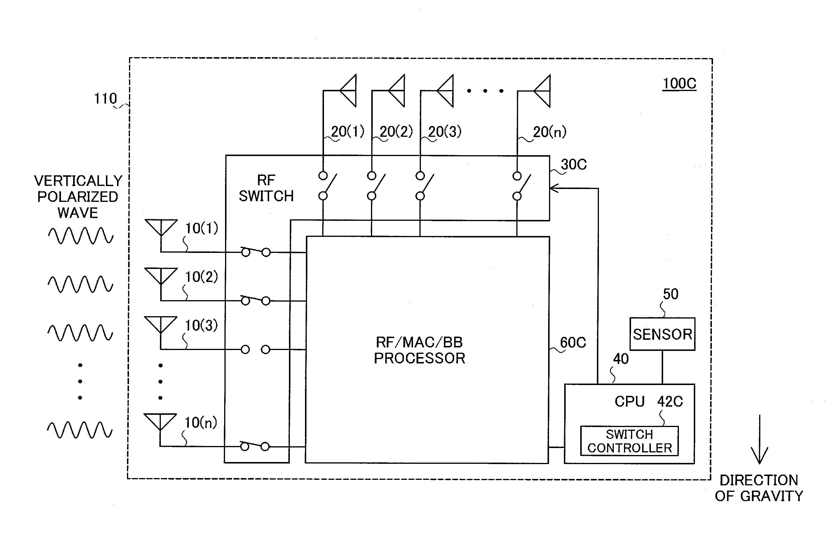
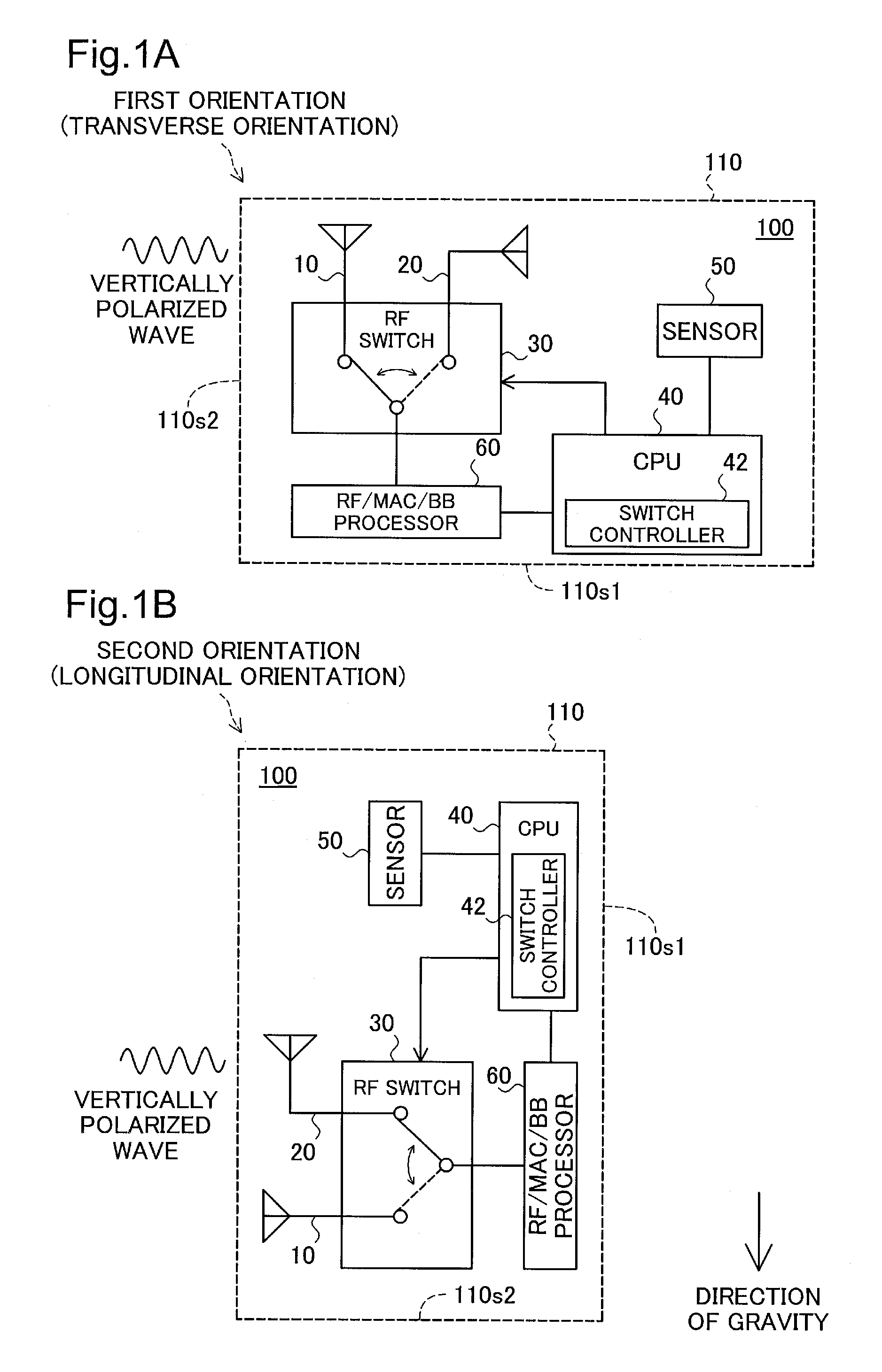
[0058]FIG. 1 is an illustration depicting the general features of an antenna unit 100 according to Embodiment 1 of the present invention. As shown, the antenna unit 100 of the present embodiment is furnished with a chassis 110 of rectangular shape in cross section. The antenna unit 100 may be used in a first orientation (transverse orientation) in which the plane that includes the long side 110s1 of the rectangular cross section of the chassis 110 is orthogonal to the direction of gravity as depicted in FIG. 1A; or in a second orientation (longitudinal orientation) in which the plane that includes the short side 110s2 of the rectangular cross section of the chassis 110 is orthogonal to the direction of gravity as depicted in FIG. 1B.

[0059]The antenna unit 100 includes a first antenna 10, a second antenna 20, an RF switch 30, a CPU 40, a sensor 50, and an RF / MAC / BB processor 60. The CPU 40 include a switch controller 42.

[0060]The first antenna 10 in the antenna unit 10...

embodiment 2

B. Embodiment 2

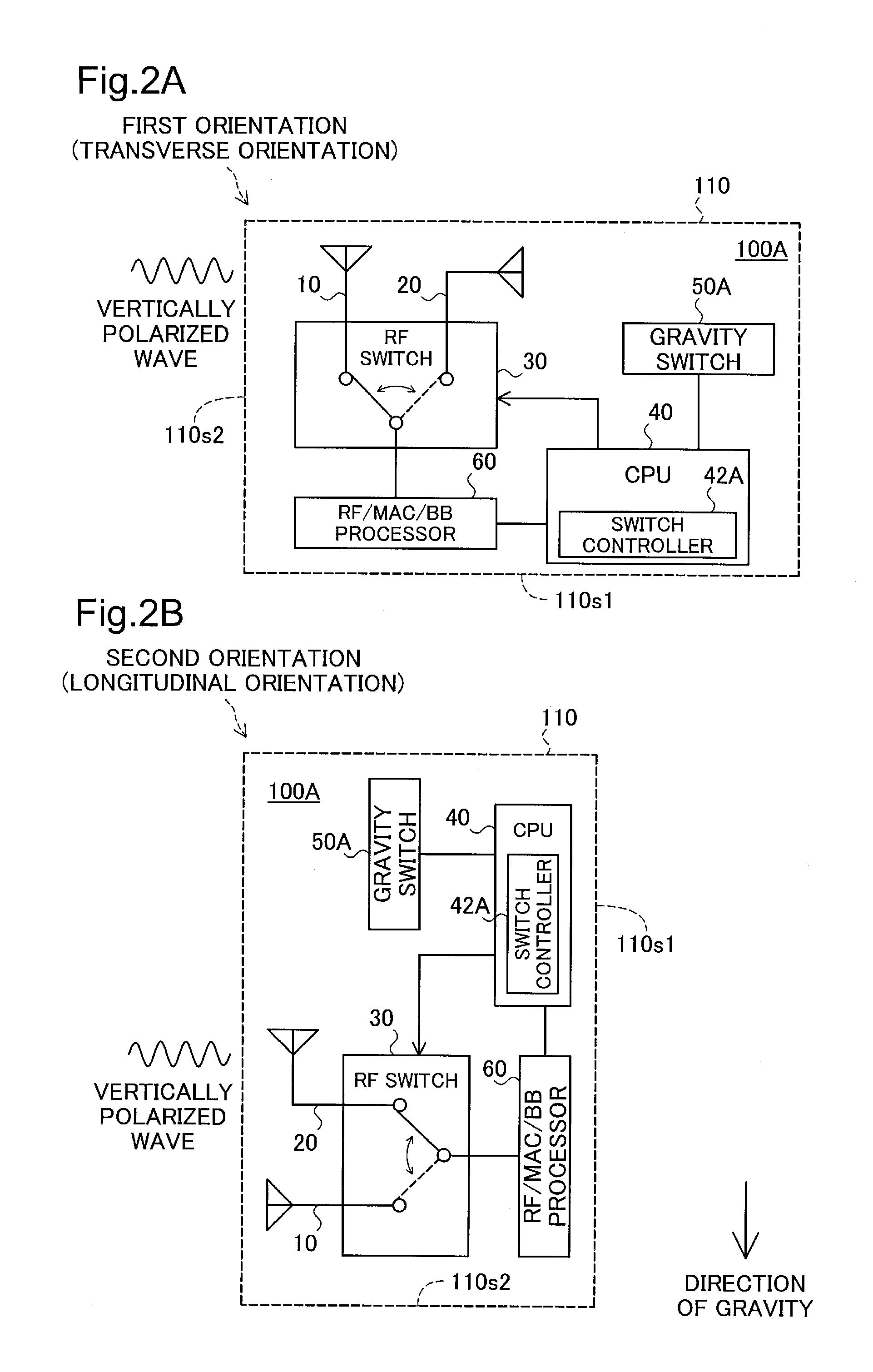
[0067]FIG. 2 is an illustration depicting the general features of an antenna unit 100A according to Embodiment 2 of the present invention. As will be apparent from a comparison of FIG. 2 with FIG. 1, the antenna unit 100A of the present embodiment is provided with a gravity switch 50A in place of the sensor 50 in the antenna unit 100 of Embodiment 1. Also, the CPU 40 of the antenna unit 100A of the present embodiment is provided with a switch controller 42A in place of the switch controller 42 in the antenna unit 100 of Embodiment 1. Other features of the antenna unit 100A are identical to the features of the antenna unit 100 of Embodiment 1.

[0068]The gravity switch 50A is a switch that changes between the open and closed state, depending on the direction in which gravity is acting. In the present embodiment, the gravity switch 50A in the antenna unit 100A assumes the closed state when the antenna unit 100A is oriented transversely, and assumes the open state when the...

embodiment 3

C. Embodiment 3

[0071]FIG. 3 is an illustration depicting the general features of an antenna unit 100B according to Embodiment 3 of the present invention. As will be apparent from a comparison of FIG. 3 with FIG. 1, the antenna unit 100B of the present embodiment is provided with a user-operated control switch 50B in place of the sensor 50 in the antenna unit 100 of Embodiment 1. Also, the CPU 40 of the antenna unit 100B of the present embodiment is provided with a switch controller 42B in place of the switch controller 42 in the antenna unit 100 of Embodiment 1. Other features of the antenna unit 100B are identical to the features of the antenna unit 100 of Embodiment 1.

[0072]As depicted in model form in the drawings, the control switch 50B in the present embodiment is a slide switch in which the point of contact is switched through sliding of the position of a lever by the user. If the antenna unit 100B is oriented transversely, the user slides the lever of the control switch 50B t...


PUM


Abstract

The antenna unit 100 includes a first antenna 10 positioned so as to face in the direction of gravity when the unit is oriented transversely, and a second antenna 20 positioned so as to face in the direction of gravity when the unit is oriented longitudinally. Based on the output of a sensor 50 that detects whether the antenna unit 100 is oriented transversely or oriented longitudinally, a switch controller 42 performs switching of an RF switch 30 so that the first antenna is used for reception or transmission of vertically polarized waves when the antenna unit 100 is oriented transversely, and the second antenna is used for reception or transmission of vertically polarized waves when the antenna unit 100 is oriented longitudinally.

Description

BACKGROUND[0001]1. Technical Field[0002]The present invention relates to an antenna unit.[0003]2. Related Art[0004]Wireless communications devices are equipped with an antenna unit for transmission and reception of radio waves to and from other wireless communications devices. In antenna units of this kind, it is preferable for example for the orientation of the antenna provided to the antenna unit to be maintained in the direction of gravity in order to provide good transmission and reception of vertically polarized waves. Additionally, it is preferable for the orientation of the antenna provided to the antenna unit to be maintained in the horizontal direction (the direction orthogonal to the direction of gravity) in order to provide good transmission and reception of horizontally polarized waves.[0005]Various techniques were proposed in the past for achieving good transmission and reception of radio waves in antenna units. For example, a mobile communications device with an intern...

Claims


Application Information

Patent Timeline
IPC IPC(8): H01Q3/00
CPCH01Q21/28H04B7/10H04B7/0834
Inventor ONO, AKIRA
Owner BUFFALO CORP LTD
Why Eureka
Try Eureka