Detecting apparatus, calculating apparatus, measurement apparatus, detecting method, calculating method, transmission system, program, and recording medium

a technology of calculating apparatus and detection apparatus, which is applied in the direction of line-transmission details, multi-frequency code systems, transmission monitoring, etc., can solve the problems of large error, distortion of reconstructed signal, and difference in phase offs

Inactive Publication Date: 2010-10-21
ADVANTEST CORP
View PDF4 Cites 15 Cited by
  • Summary
  • Abstract
  • Description
  • Claims
  • Application Information

AI Technical Summary

Problems solved by technology

Furthermore, a difference in phase offset occurs due to the frequency dependency in each channel.
As a result, when the signal transmitted by these different channels is reconstructed, there is distortion in the reconstructed signal.
When detecting the time difference and the phase offset independently, however, there is a large error.

Method used


Image

  • Detecting apparatus, calculating apparatus, measurement apparatus, detecting method, calculating method, transmission system, program, and recording medium
  • Detecting apparatus, calculating apparatus, measurement apparatus, detecting method, calculating method, transmission system, program, and recording medium
  • Detecting apparatus, calculating apparatus, measurement apparatus, detecting method, calculating method, transmission system, program, and recording medium

Examples


first embodiment

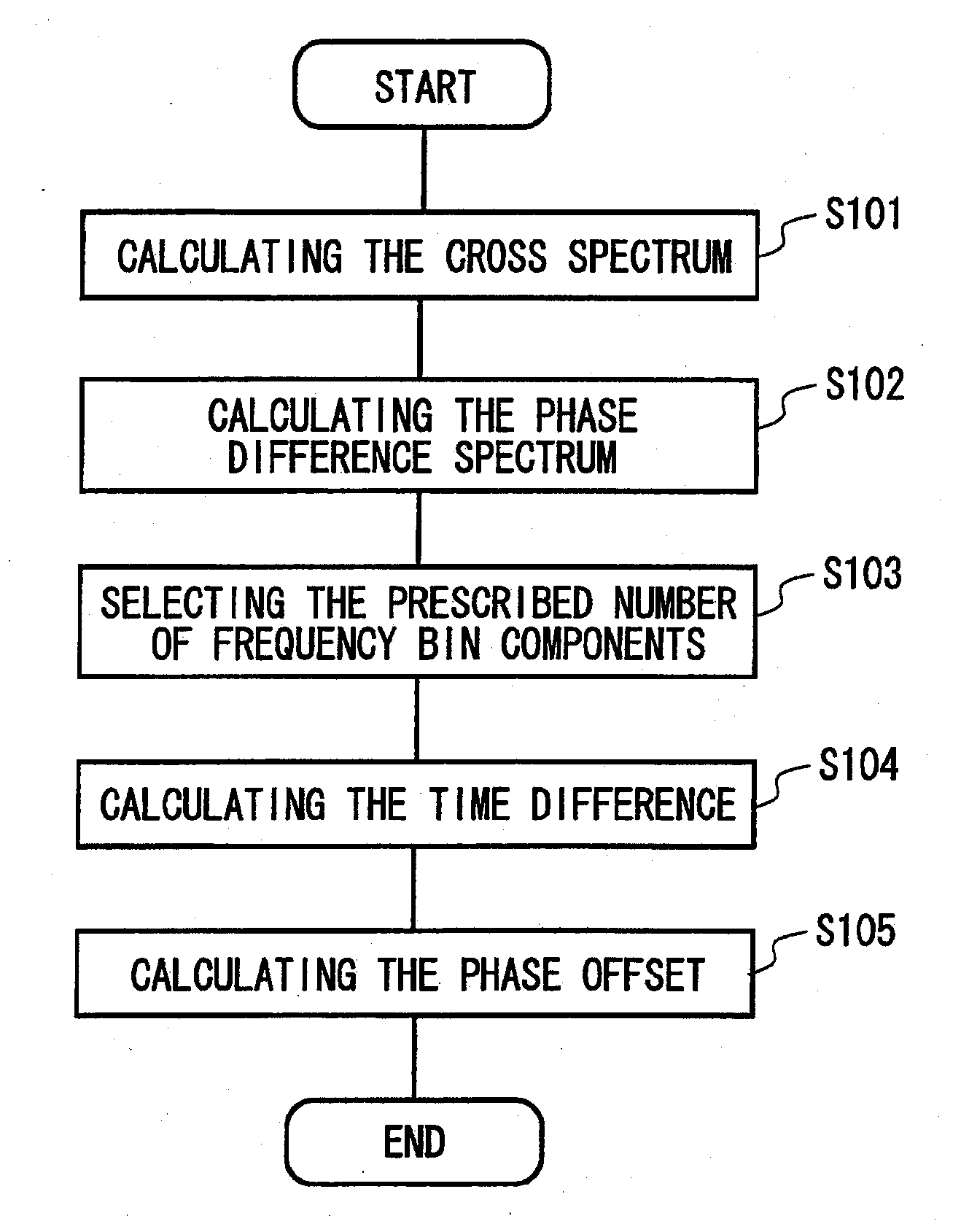
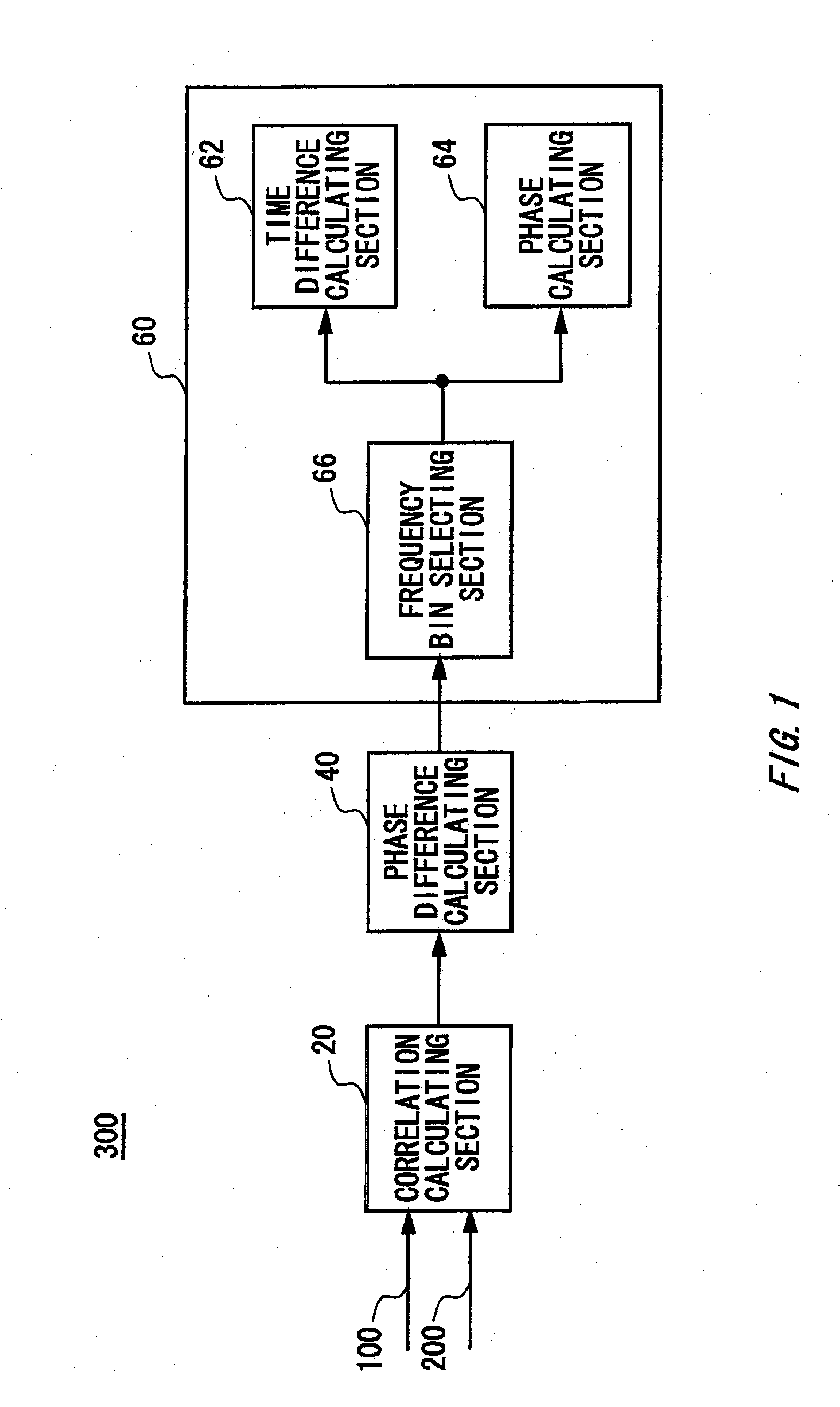
[0034]FIG. 1 shows a configuration of a detection apparatus 300 according to the present invention. The detection apparatus 300 is provided with a correlation calculating section 20, a phase difference calculating section 40, and a detecting section 60. A channel 100 and a channel 200 are connected to the correlation calculating section 20. For example, the channel 100 and the channel 200 each may include a transmission line having a different frequency characteristic. The detection apparatus 300 detects a phase alignment error between transmission signals transmitted on the channel 100 and the channel 200. Here, the phase alignment error refers to an error caused by a time difference and a phase offset occurring between a plurality of signals.

[0035]The correlation calculating section 20 calculates a cross spectrum between transmission signals, based on the result of the measurement of each transmission signal transmitted on a corresponding channel. The phase difference calculating ...

second embodiment

[0065]FIG. 5 shows a configuration of the detection apparatus 300 according to the present invention. The detection apparatus 300 of the present embodiment is provided with a measuring section 80 in addition to the configuration shown in FIG. 1. The measuring section 80 samples the transmission signal transmitted on each channel and performs a Fourier transform on the sampling result of each transmission signal.

[0066]The measuring section 80 may simultaneously or sequentially measure a plurality of transmission signals transmitted on the channel 100 and the channel 200.

third embodiment

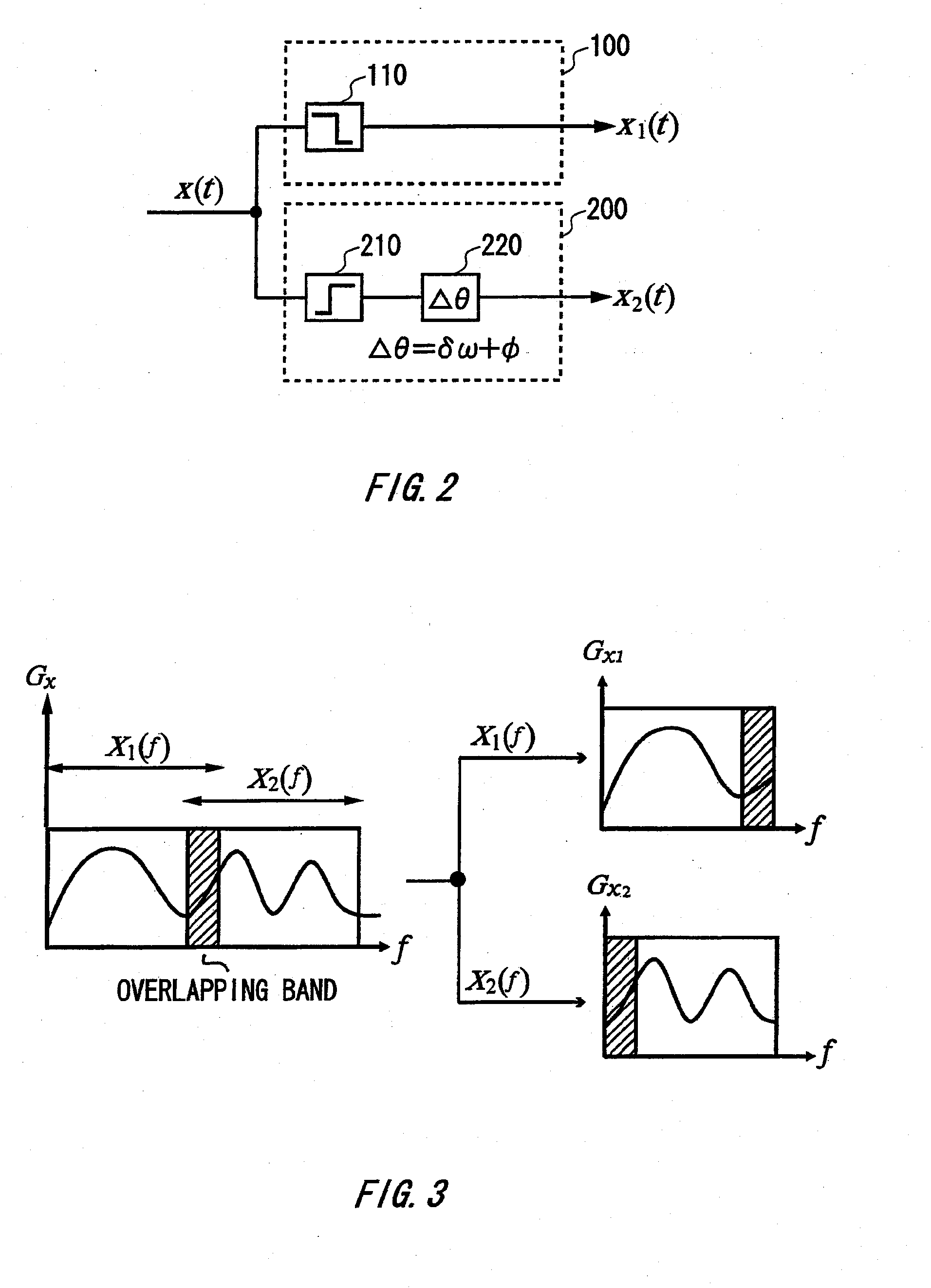
[0067]FIG. 6 shows a configuration of the detection apparatus 300 according to the present invention. The detection apparatus 300 is provided with a signal sending section 90 in addition to the configuration shown in FIG. 1. The signal sending section 90 inputs, to the channel 100 and the channel 200, transmission signals having substantially the same spectrum in the prescribed overlapping frequency band.

[0068]The signal sending section 90 may use a lowpass filter and a highpass filter having an overlapping signal-pass frequency to divide a single signal to generate the transmission signals that are input to the channel 100 and the channel 200, respectively. By generating a plurality of transmission signals and inputting these signals into a plurality of channels, the detection apparatus 300 can measure characteristics of the plurality of channels without connecting an apparatus for generating the transmission signals.


PUM


Abstract

Provided is a detection apparatus that detects a phase alignment error between transmission signals transmitted on different channels, comprising a correlation calculating section that calculates a cross-spectrum between the transmission signals based on a result of a measurement of the transmission signals transmitted in the channels; a phase difference calculating section that calculates a phase difference spectrum between the transmission signals based on the cross-spectrum calculated by the correlation calculating section; and a detecting section that detects a difference between transmission times of the transmission signals transmitted on the different channels and a phase offset between the transmission signals, based on the phase difference spectrum calculated by the phase difference calculating section.

Description

BACKGROUND[0001]1. Technical Field[0002]The present invention relates to a detection apparatus, a calculation apparatus, a measurement apparatus, a detecting method, a calculating method, a transmission system, a program, and a recording medium.[0003]2. Related Art[0004]A broadband signal is sometimes transmitted using a plurality of channels having different frequency bands. If the line length of each channel is different, there is a difference in transmission time for each channel. Furthermore, a difference in phase offset occurs due to the frequency dependency in each channel. As a result, when the signal transmitted by these different channels is reconstructed, there is distortion in the reconstructed signal.[0005]The time difference can be detected by applying a measurement pilot signal to each channel and measuring the amount of time necessary for the pilot signal to be output from each channel. The phase offset can be detected by using the phase of the pilot signal output fro...

Claims


Application Information

Patent Timeline
Patent Type & Authority Applications(United States)
IPC IPC(8): H04B3/46
CPCH04L27/0014H04B3/46
Inventor AOKI, TAKAFUMIYAMAGUCHI, TAKAHIRODEGAWA, KATSUHIKO
Owner ADVANTEST CORP
Why Eureka
Try Eureka