Image decoding device

Active Publication Date: 2010-10-21
SOVEREIGN PEAK VENTURES LLC
View PDF33 Cites 21 Cited by
  • Summary
  • Abstract
  • Description
  • Claims
  • Application Information

AI Technical Summary

Benefits of technology

[0016]The image decoding apparatus having the above-stated structure is capable of selecting, for each of the plurality of pieces of partial data composing image data, a decoder which is caused to perform decoding based on an attribute that affects time taken to perform such decoding processing. Therefore, when each of the plurality of pieces of partial data is decoded by a corresponding one of the plurality of decoders in parallel, it is possible to suppress imbalance of decoding processing time between each decoder, which makes it possible to enhance processing efficiency.
[0017]That is, time that the decoders do not perform the decoding processing is shortened by determining which of the decoders is caused to decode which piece of the plurality of pieces of partial data so as to reduce variation in processing time between each of the decoders, which makes it possible to realize efficiency of decoding processing of image data.
[0018]Also, since a plurality of pieces of partial data composing image data are processed in parallel, it is possible to accurately decode even image data that would need to be decoded by a decoder having higher processing ability than any of the individual decoders under ordinary circumstances.
[0019]Furt

Problems solved by technology

However, when decoding is performed by one decoder, high-computing performance and a broad data b

Method used


Image

  • Image decoding device
  • Image decoding device
  • Image decoding device

Examples


first embodiment

Outline

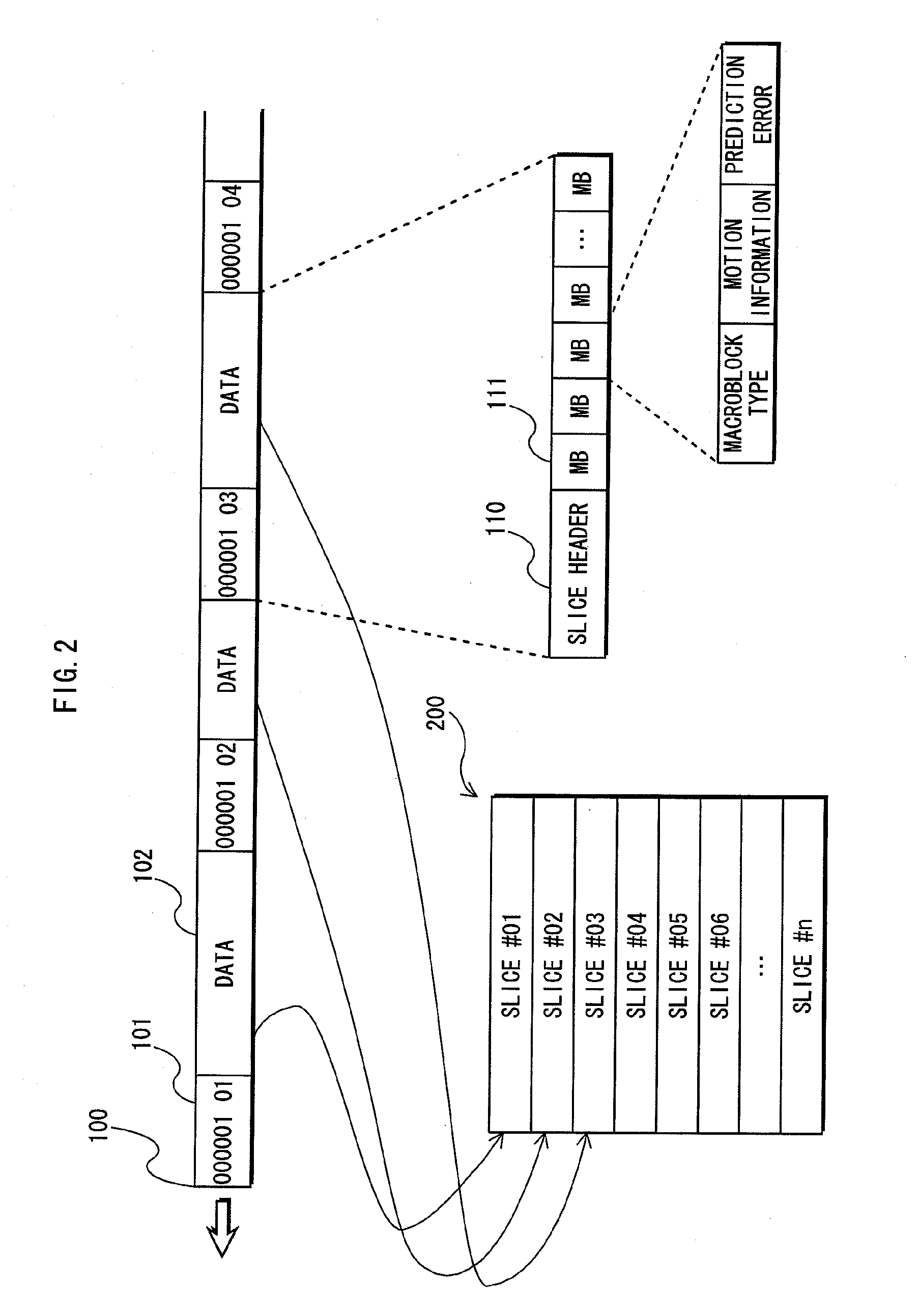
[0073]The image decoding apparatus pertaining to the present invention reduces vacant time of each decoder, and causes the decoders to perform efficient decoding processing by dividing a bitstream (hereinafter, “image data”) of encoded images into predetermined units (e.g. units of slices), and distributing the units of slices to the decoders according to a characteristic of each slice.

[0074]Also, the present image decoding apparatus can respond to changes in the number of decoders by acquiring processing performance of each decoder at appropriate timings, and also can perform decoding processing more efficiently by distributing slices based on processing ability of each decoder.

[0075]The following describes an image decoding apparatus in an embodiment of the present invention using the drawings. Note that the embodiment describes the case where image data created according to the MPEG-2 standard is decoded.

Functions

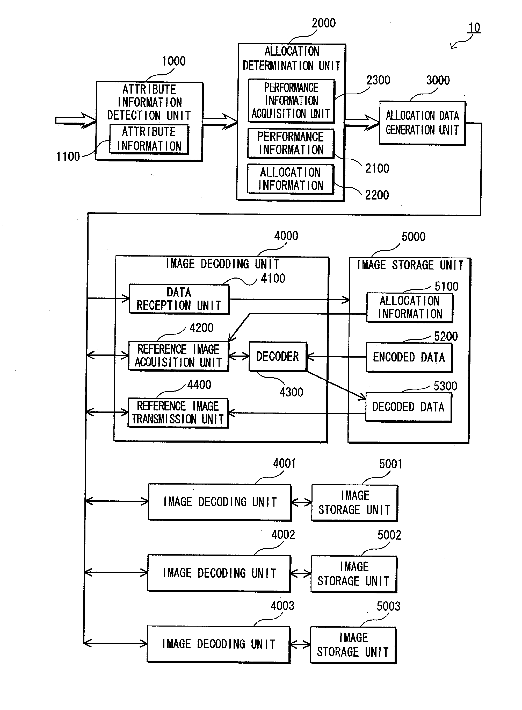
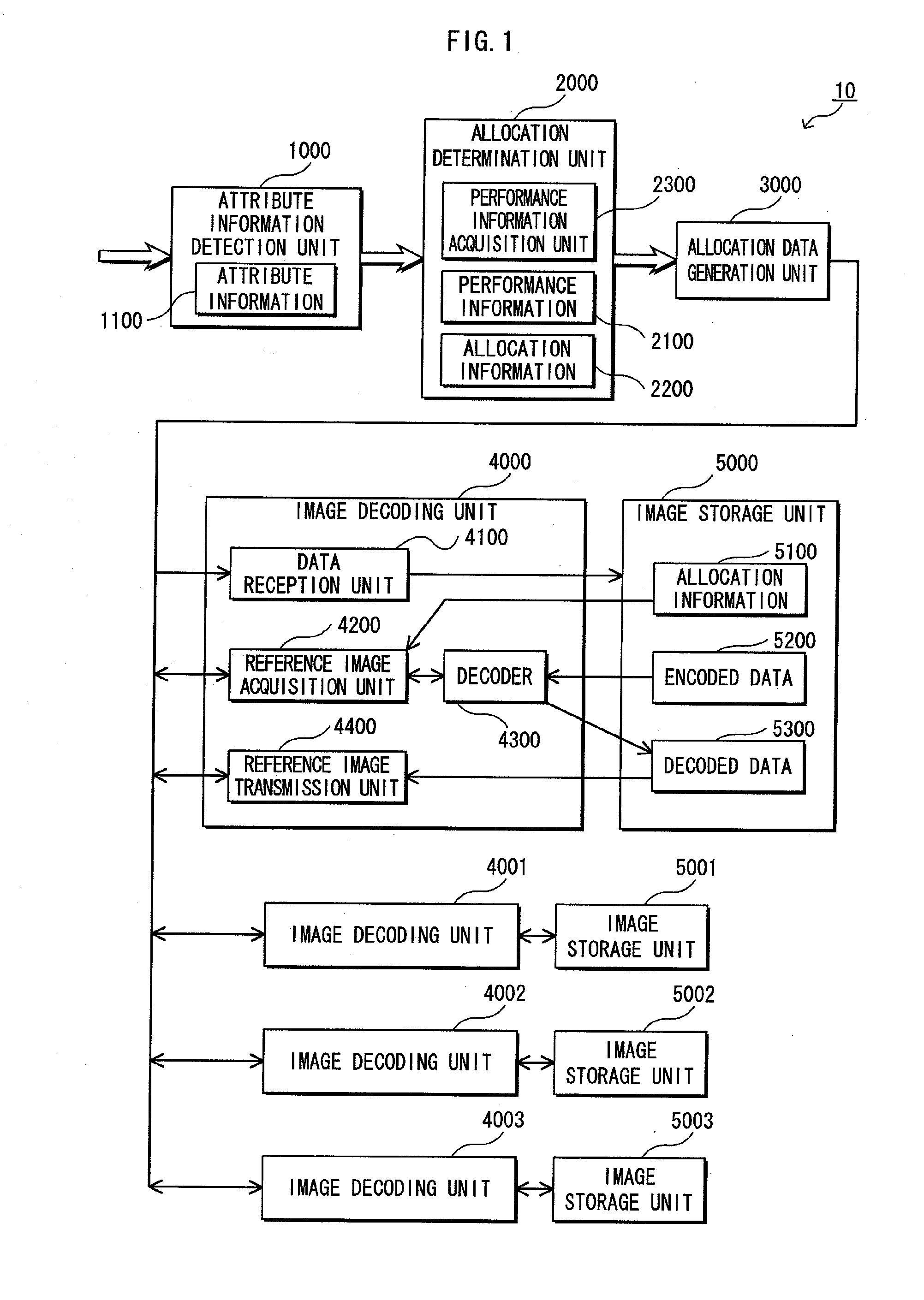
[0076]FIG. 1 is a block diagram showing a structure of an im...

second embodiment

Outline

[0183]In the first embodiment, allocation to each of the image decoding units is performed in units of slices based on the data amount of each slice. However, the present embodiment describes an example of performing allocation to each of the image decoding units in units of pictures based on a type of each picture (I, P, B). Of course, allocation may be performed in units of slices based on a type of each slice. However, a description is given of the case of performing allocation in units of pictures for convenience.

[0184]Pictures in the MPEG-2 standards have the following three types.

[0185]The three types of pictures are I-picture on which in-screen prediction is performed, P-picture on which forward prediction is performed from a past picture, and B-picture on which bidirectional prediction is performed from the past picture and a future picture.

Function

[0186]A structure of an image decoding apparatus of the present embodiment is the same as the structure of the image deco...

third embodiment

[0223]FIG. 16 is a block diagram of an image decoding apparatus 20 of the present embodiment.

[0224]Although each of the image decoding units (4000, 4001, 4002 and 4003) includes each of the image storage units (5000, 5001, 5002 and 5003), respectively in the first embodiment, the present embodiment is different from the first embodiment only in that the image decoding units share one image storage unit 5900.

[0225]In the first embodiment, each of the image storage units (5000 and the like) stores therein the allocation information 5100, the encoded data 5200 and the decoded data 5300 (see FIG. 1).

[0226]In the present embodiment, a region is allocated to each of the image decoding units (4000 and the like) in the image storage unit 5900, and the image decoding units 4000 to 4003 share the decoded data 5300. Here, the region is for storing the allocation information 5100 and the encoded data 5200. Note that the image decoding units 4000 to 4003 may share the allocation information 5100...


PUM


Abstract

An image decoding apparatus pertaining to the present invention includes a plurality of decoders. The image decoding apparatus (i) divides image data to decode into a plurality of pieces of partial data, (ii) acquires attribute information pieces each affecting decoding processing time of a corresponding one of the plurality of pieces of partial data, (iii) determines which of the plurality of decoders is caused to decode which of the plurality of pieces of partial data based on the attribute information pieces on the plurality of pieces of partial data and (iv) causes two or more of the plurality of decoders to decode two or more corresponding pieces of the partial data in parallel.

Description

TECHNICAL FIELD[0001]The present invention relates to an image decoding apparatus that decodes encoded image data, and in particular to technology that enhances decoding processing speed when decoding is performed by a plurality of decoders in parallel.BACKGROUND ART[0002]In recent years, the data amount of images, especially moving images, has been increasing in order to satisfy high-definition and large-screen requirements. Therefore, technology that compresses and encodes moving picture data has been developed in view of the following cases or the like: where such moving picture data which has been increasing in amount is transmitted on a network, and where moving picture data is stored in a storage medium.[0003]For example, there are international standards such as the MPEG-2 (Motion Picture Experts Group), the H264 / MPEG-4AVC (Advanced Video Codec) and the like.[0004]Moving picture data that has been encoded according to these standards is usually displayed while being decoded b...

Claims


Application Information

Patent Timeline
IPC IPC(8): H04N7/12
CPCH04N19/176H04N19/70H04N19/61H04N19/436H04N19/174H04N19/44H04N19/156
Inventor HASHIMOTO, TAKASHIWADA, YOSHIYUKI
Owner SOVEREIGN PEAK VENTURES LLC
Why Eureka
Try Eureka