Unobstructed low pressure outlet and screen grid for a high pressure feeder

a high-pressure feeder, unobstructed technology, applied in the field of high-pressure feeders, can solve the problems of reducing the capacity and efficiency of a hpf, and achieve the effects of enhancing the flow of wood chips, facilitating the flow through and out of the rotor, and reducing the pressure in the flow passing

Active Publication Date: 2010-10-21
ANDRITZ INC
View PDF44 Cites 16 Cited by
  • Summary
  • Abstract
  • Description
  • Claims
  • Application Information

AI Technical Summary

Benefits of technology

[0008]An unobstructed flow of liquor to the low pressure outlet would allow for liquor to more easily flow through and out of the rotor. Allowing the liquor to flow through and out of the rotor without obstruction enhances the flow of wood chips through the HPF and to the high pressure outlet of the HPF. An unobstructed flow of liquor through the low pressure outlet would lower the pressure in the flow passing through the rotor while the rotor is aligned with the low pressure inlet to the HPF. An unobstructed flow of liquor through the low pressure outlet would increase the amount of chips that fill the rotor as the low pressure slurry of chips and liquor enters the HPF and the rotor.
[0009]There is a long felt need to improve the efficiency and capacity of HPFs. Obstructions to the low pressure outlet flow in a HPF tend to reduce the capacity and efficiency of a HPF. Increasing the capacity of HPFs allows for greater amounts of wood chips to flow through and be pressurized by the HPF. Reducing the obstructions to the low pressure outlet tends to increase the efficiency of the HPF by increasing the capacity of the HPF without requiring an increase in power applied to drive the HPF.
[0010]The slots in the screen grid have been increased to form a large single continuous slotted area in the screen grid which corresponds to the entire area of the low pressure outlet and to the areas of the ports in the rotor. The portion of casing for the drive coupling of the rotor may be decreased in size, e.g. by one inch (25 mm), to allow for an expansion of the open area of the low pressure outlet in the casing and allow for a larger slotted surface area of the screen grid. The center bar in the low pressure outlet of the liner may be removed. The expanded outlet of the casing and the screen grid slotted surface allow for an increase flow of low pressure liquid through the outlets in the pocketed rotor and out of the HPF. The fluid flow through the slots contributes to the increased efficiency of the screen grid.
[0012]Further, by increasing the slot opening width to between 8 millimeters (mm) to 25 mm in the screen grid and increasing the area of the slots region in the screen grid, the capacity and efficiency of the flow of liquid through the screen grid is increased.

Problems solved by technology

Obstructions to the low pressure outlet flow in a HPF tend to reduce the capacity and efficiency of a HPF.

Method used


Image

  • Unobstructed low pressure outlet and screen grid for a high pressure feeder
  • Unobstructed low pressure outlet and screen grid for a high pressure feeder
  • Unobstructed low pressure outlet and screen grid for a high pressure feeder

Examples


Embodiment Construction

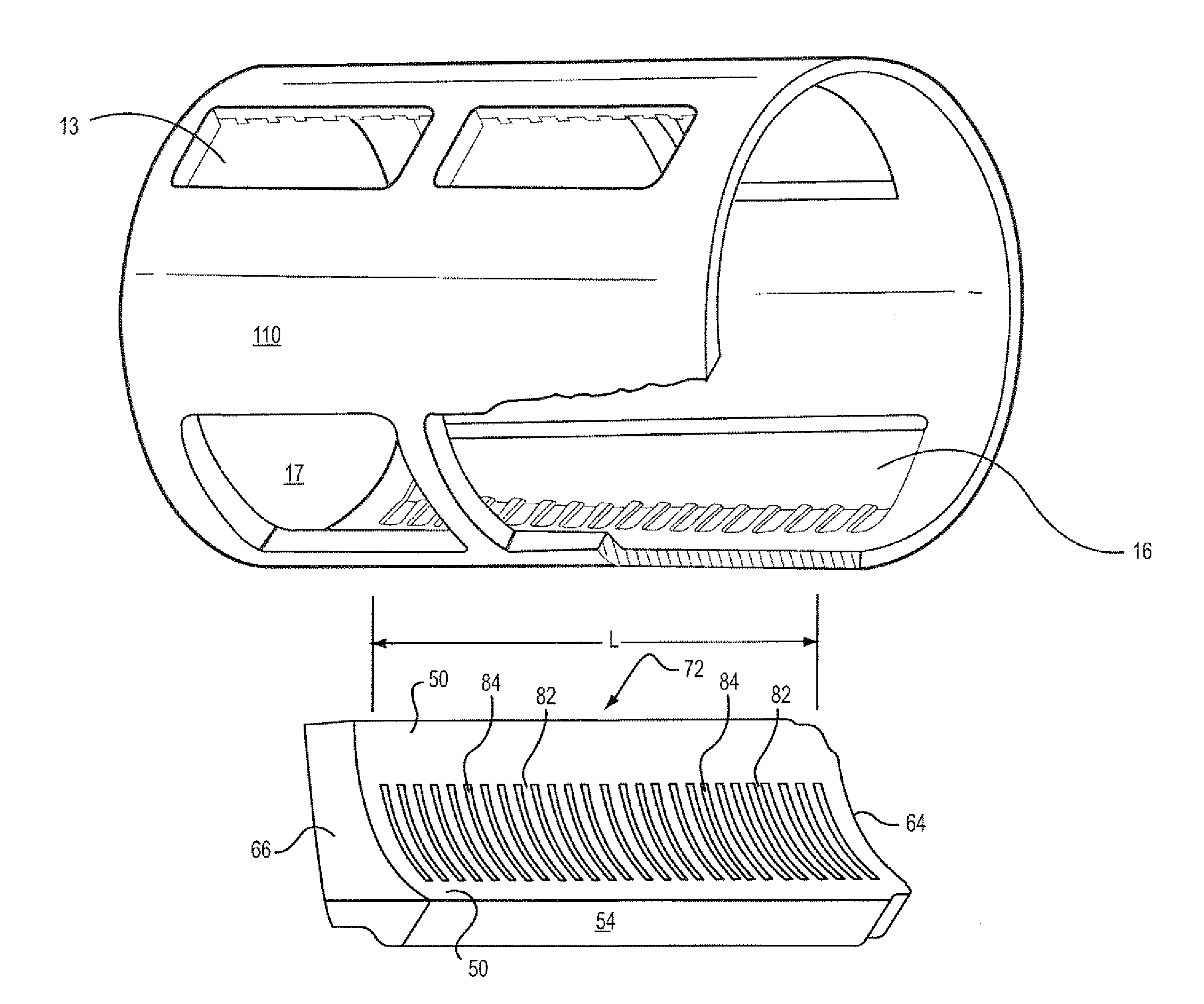
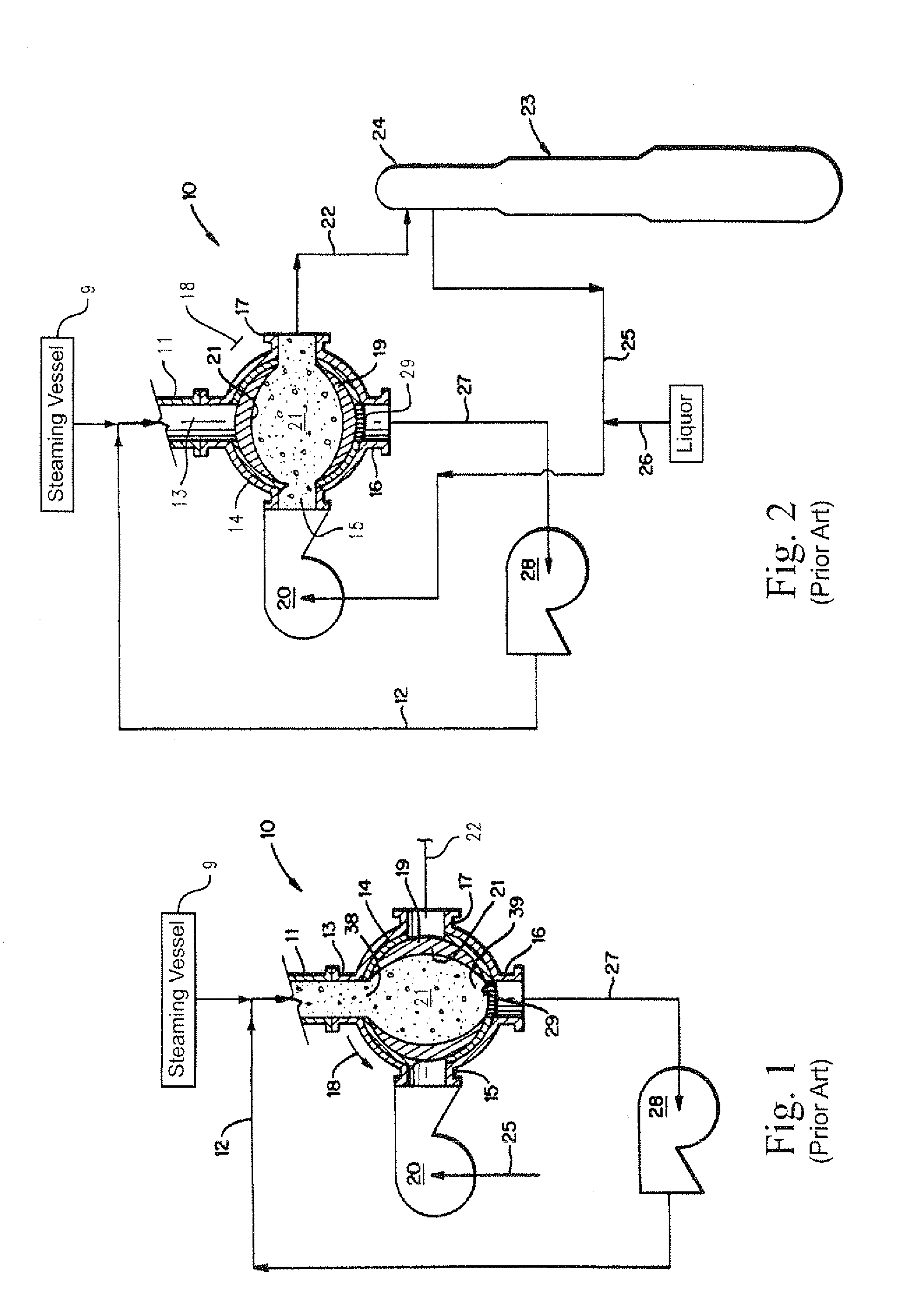
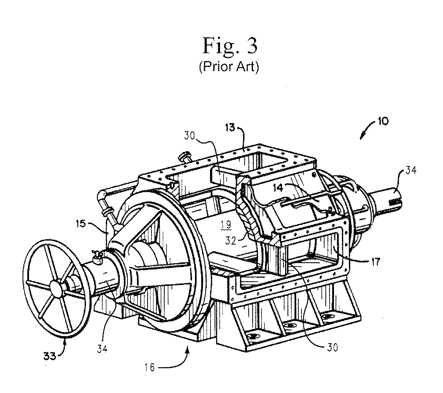
[0023]FIGS. 1 and 2 schematically illustrate the operation of a high pressure transfer device, which is also referred to as a high pressure feeder (HPF) 10. As is conventional, the HPF 10 is connected to a chip chute 11, which is supplied with steamed wood chips (or other cellulosic material) from a conventional steaming vessel 9, the chips are slurried with liquid (liquor) from a liquid supply conduit 12. The chute 11 is connected to a first port (low pressure inlet) 13 of a housing (casing) of the HPF 10. The housing also has a second port (high pressure inlet) 15, a third port (low pressure outlet) 16, and a fourth port (high pressure outlet) 17. These ports 13, 15, 16 and 17 are disposed around the casing 14 at intervals of approximately 90 degrees. A pocketed rotor 19 rotates (see direction of rotation 18) within the housing 14.

[0024]The rotor 19 typically has four pockets 21 that each form a flow passage extending through the rotor in a direction perpendicular to the axis of r...


PUM


Abstract

A rotary high pressure feeder for processing cellulosic fibrous material including: a rotor rotatable about an axis and comprising at least one pocket comprising a conduit extending through the rotor in a direction perpendicular to the axis and having end openings at opposite ends of the pocket, wherein each of said end openings of each pocket functions as both an inlet and outlet depending upon an angular position of the rotor within a housing; the housing encloses said rotor and said housing includes a low pressure inlet port and a low pressure outlet port aligned vertically, and a high pressure inlet port and a high pressure outlet port aligned horizontally, wherein the ports are arranged on the housing for registry with the end openings of at least one pocket, and a screen grid seated in or adjacent to the low pressure outlet port, wherein the screen grid includes an array of screen slots and bars forming a uniform pattern of slots and bars extending without interruption across an entirety of the low pressure outlet port.

Description

RELATED APPLICATION[0001]This application claims the benefit of U.S. Provisional Patent Application Ser. No. 61 / 169,378 filed on Apr. 15, 2009, the entirety of which is incorporated by reference.BACKGROUND OF THE INVENTION[0002]The present invention relates to high pressure feeders (HPF) typically used to pressurize slurries of comminuted cellulosic material, such as wood chips. The present invention particularly relates to screens that retain cellulosic material in the rotor of the HPF and allow liquid to be discharged through a low pressure outlet of the HPF.[0003]High pressure feeders are typically included in chip feed systems that deliver a high pressure slurry of wood chips to a pressurized digester vessel, such as used in Kraft pulping. HPFs are described in U.S. Pat. Nos. 4,107,843; 6,120,646; 5,236,285, 6,468,006 and 6,616,384, and in published international patent applications WO 94 / 21855 and WO 99 / 42653.[0004]HPFs typically have a rotor with four through passages that fil...

Claims


Application Information

Patent Timeline
Patent Type & Authority Applications(United States)
IPC IPC(8): B65G53/46
CPCD21C7/06D21C3/24
Inventor VOGEL, KEITHLUHRMANN, CARL
Owner ANDRITZ INC
Why Eureka
Try Eureka