Pin or socket contact with resilient clip

a resilient clip and pin or socket technology, applied in the manufacture of contact members, coupling contact members, contact members penetrating/cutting insulation/cable strands, etc., can solve the problems of difficult to open the contact point in confined spaces, relatively difficult disconnection, etc., to facilitate the connection and disconnection of the conductor

Inactive Publication Date: 2010-10-21
WEIDMULLER INTERFACE GMBH & CO KG
View PDF12 Cites 30 Cited by
  • Summary
  • Abstract
  • Description
  • Claims
  • Application Information

AI Technical Summary

Benefits of technology

[0007]In one embodiment, the spring clip portion is bifurcated to define a pair of parallel spaced resilient struts the upper ends of which are reversely bent toward each other. A synthetic plastic operating member is provided having a pair of tab portions that are manually squeezed together on opposite sides of the struts, thereby to pivot the reversely-bent end portions apart about an intermediate stop portion to the separated condition. The stop portion also serves to limit the extent to which the bare conductor end is longitudinally inserted into the spring clip end of the connector. An annular guide collar may be provided for longitudinally guiding the conductor relative to the connector. Limiting means on the operating member serve to limit the extent of separation of the struts.
[0009]As a consequence of the invention, a user may easily connect and disconnect a conductor from a jack or socket connector.

Problems solved by technology

DE 2717402, disconnection is relatively difficult due to the plurality of shock-absorbing struts.
DE 102005053566 A1, it is under certain circumstances also difficult to open the contact point in confined spaces.

Method used


Image

  • Pin or socket contact with resilient clip
  • Pin or socket contact with resilient clip
  • Pin or socket contact with resilient clip

Examples


Embodiment Construction

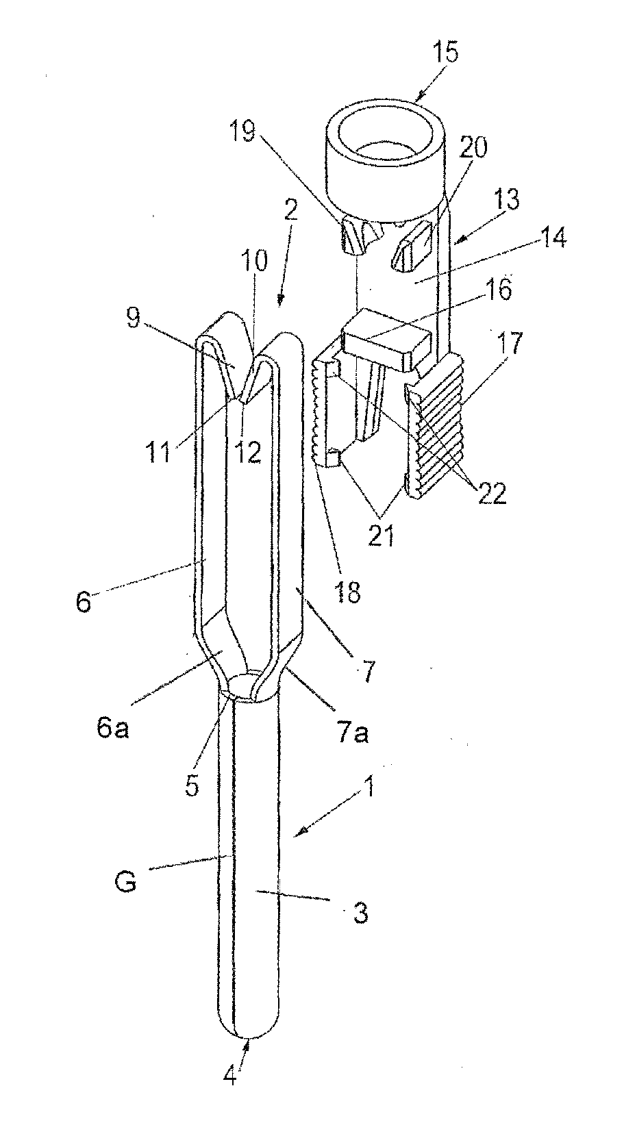
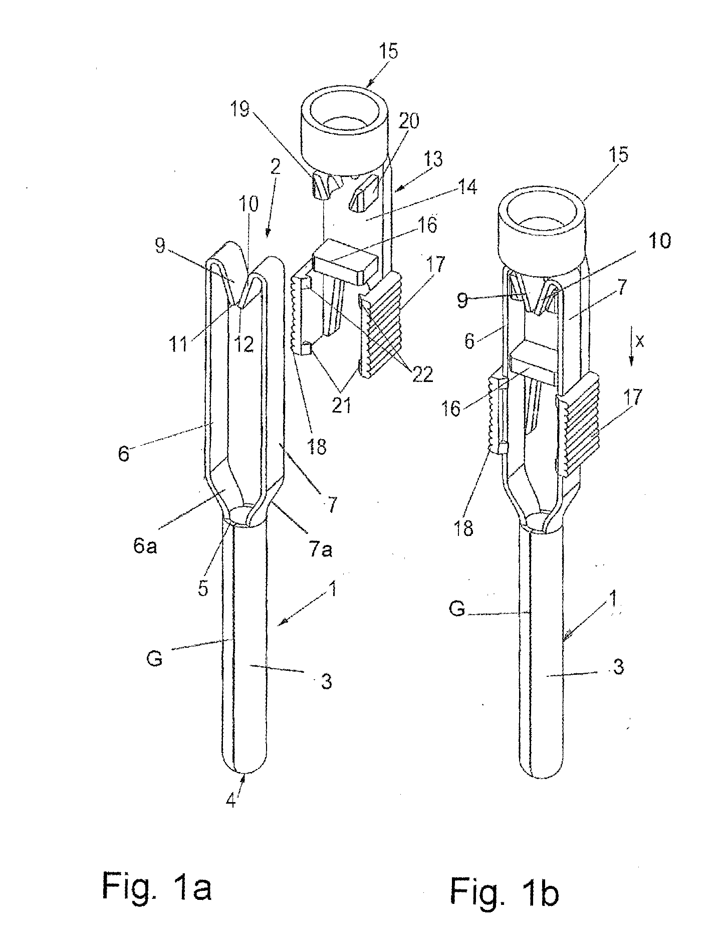
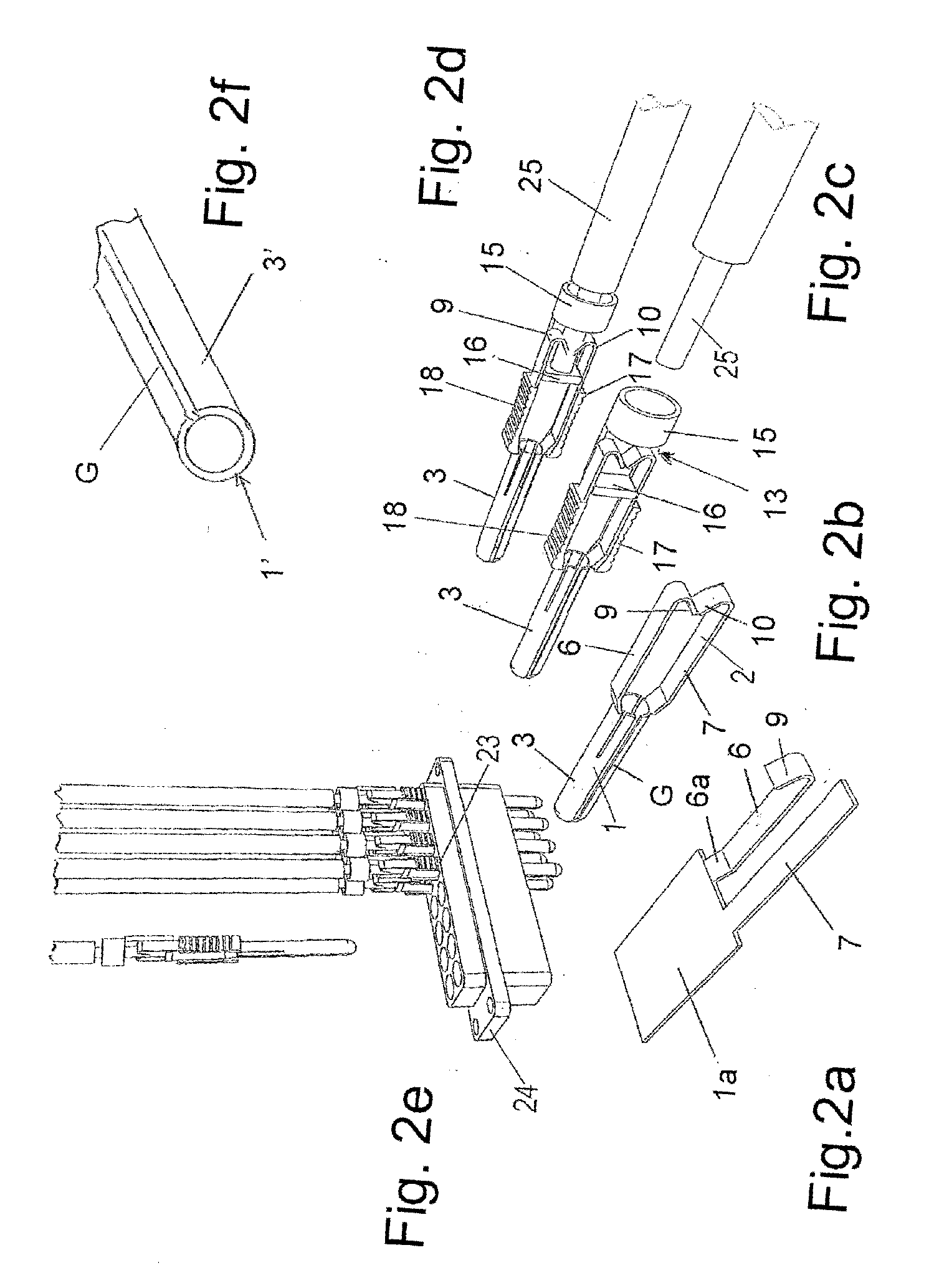
[0017]Referring first more particularly to FIGS. 1a and 1b, the electrical jack terminal or connector 1 includes a vertical tubular body portion 3 connected at its upper end 5 with a bifurcated spring clip portion 2 including a pair of parallel spaced resilient strut 6 and 7 portions that terminate at their upper ends in reversely-bent inwardly-directed angular contact portions 9 and 10 having opposed terminal edges 11 and 12, respectively. The struts are resiliently biased together to effect engagement between the contact edges 11 and 12. The lower end 4 of the tubular body portion is closed, thereby to define the male jack contact.

[0018]A synthetic plastic separating member 13 is provided having a vertical planar base portion 14 that carries intermediate its upper and lower ends an orthogonally arranged horizontal stop portion 16. The lower end of the base portion is bifurcated to define a pair of leg portions that support a pair of vertical parallel spaced resilient finger tab po...


PUM


Abstract

An electrical pin or socket terminal includes a vertical tubular body portion, and a spring clip portion connected with the upper end of the body portion. The spring clip portion includes two opposed electrical contacts at least one of which is resiliently biased toward the other. A separating arrangement is operable between a separated condition retaining the contacts in separated spaced relation for longitudinally receiving therebetween a conductor bare end, and a released condition in which the contacts are released for resilient electrical engagement with diametrically opposed surfaces of the conductor bare end. In one embodiment, the spring clip portion includes a pair of parallel spaced struts the upper ends of which are reversely bent toward each other. In another embodiment, a leaf spring electrical contact biases the bare conductor end against a stationary electrical contact.

Description

BACKGROUND OF THE INVENTION[0001]1. Field of the Invention[0002]An electrical pin or socket terminal includes a vertical tubular body portion, and a spring clip portion connected with the upper end of the body portion. The spring clip portion includes two opposed electrical contacts at least one of which is resiliently biased toward the other. A separating arrangement is operable between a separated condition retaining the contacts in separated spaced relation for longitudinally receiving therebetween a conductor bare end, and a released condition in which the contacts are released for resilient electrical engagement with the conductor bare end.[0003]2. Description of Related Art[0004]Electrical terminals of the male jack or female socket type are known in the art which are provided at one end with spring clip means for connection with the bare end of an insulated conductor, as evidenced, for example, by the German patents Nos. DE 2717402 and DE 102005053566 A1. In the case of Germa...

Claims


Application Information

Patent Timeline
Patent Type & Authority Applications(United States)
IPC IPC(8): H01R4/48
CPCH01R43/16H01R4/4818H01R13/04H01R4/48185
Inventor PUESCHNER, KLAUSWUENSCHE, TORSTENHOLTERHOFF, KLAUSWOHLGEMUTH, KLAUS
Owner WEIDMULLER INTERFACE GMBH & CO KG
Why Eureka
Try Eureka