Control method for motor-driven shears

a control method and motor technology, applied in driving apparatus, agriculture tools and machines, manufacturing tools, etc., can solve problems such as significant injury to users, mcu transmission of incorrect instructions, and unsatisfactory solutions, so as to prevent the risks caused, and improve the safety of motor-driven shears.

Inactive Publication Date: 2010-10-28
YANG DEZHONG +1
View PDF10 Cites 26 Cited by
  • Summary
  • Abstract
  • Description
  • Claims
  • Application Information

AI Technical Summary

Benefits of technology

[0006]The present invention provides an improved control method for motor-driven shears to overcome the issues and deficiencies of the prior art described above. The motor-driven shears of the present invention can effectively prevent the safety risks caused by a failure of the MCU, and thereby improve the security of the motor-driven shears.
[0007]The control method for the motor-driven shears of the present invention requires that both the power supply module and the control system used to drive the motor be active simultaneously for the shears to operate. The power supply module requires a switch be pressed to activate the power supply module and to provide the resultant power to the MCU. Further, upon releasi

Problems solved by technology

However, this proposed solution is not without issues.
If the MCU malfunctions or is damaged, the MCU may tra

Method used


Image

  • Control method for motor-driven shears
  • Control method for motor-driven shears
  • Control method for motor-driven shears

Examples


Embodiment Construction

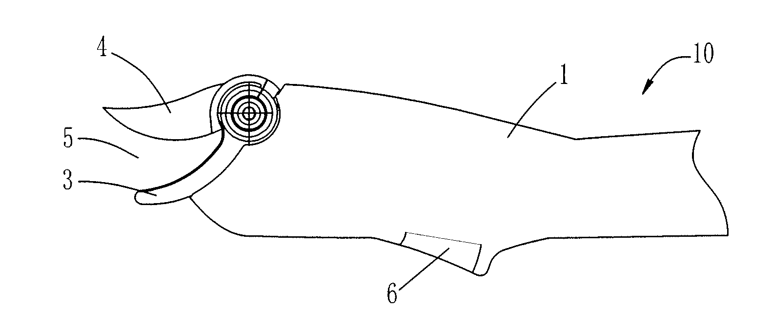
[0015]There are various shapes and kinds of the motor-driven shears. As an example, a first embodiment implements branch-pruning shears. Referring to FIG. 1, the branch-pruning shears 10 include a housing 1 in which a motor 2 (not shown) is installed. The cutter portion of the branch-pruning shears 10 is comprised of a fixed blade 3 and a movable blade 4, wherein the fixed blade 3 is fixed relative to the housing 1, and the movable blade 4 is connected to the motor 2 by a transmission device. A cutting mouth 5 is formed between the fixed blade 3 and the movable blade 4. A switch 6 is mounted on the housing 1. To allow for many different uses and various operating situations, the branch-pruning shears 10 may be powered by a battery pack (not shown) which can be disposed on an end of the housing 1.

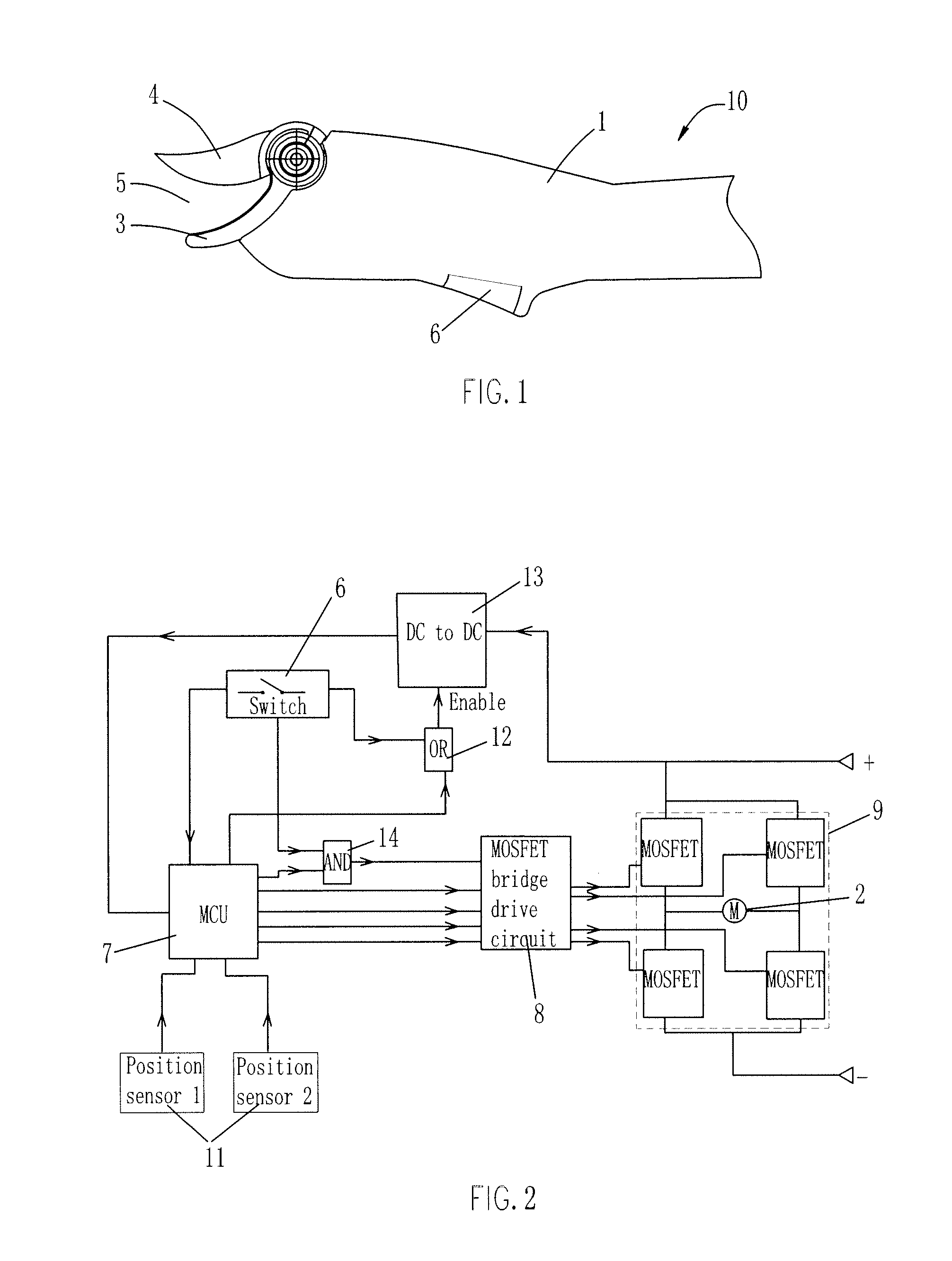
[0016]Referring to FIG. 2, it shows a circuit schematic of a first embodiment of a control system for the branch-pruning shears 10. In order to meet the requirements of the relevant safety s...


PUM


Abstract

The present invention relates to a control method for motor-driven shears. The control method for the motor-driven shears of the present invention requires that both the power supply module and the control system used to drive the motor be active simultaneously for the shears to operate. The power supply module requires a switch be pressed to activate the power supply module and to provide the resultant power to the MCU. Further, upon releasing the switch, the MCU is be able to maintain the power supply module in a discharging state long enough to allow the control system controlling the motor to rotate the movable blade to an open position. Finally, when the movable blade is opened to a maximum position, the MCU may direct the motor to stop rotation and shut off the power supply module.

Description

CROSS-REFERENCE TO RELATED APPLICATIONS[0001]This application claims priority under 35 U.S.C. §119 to CN 200910031464.8 filed Apr. 28, 2009, which is hereby incorporated by reference.FEDERALLY SPONSORED RESEARCH OR DEVELOPMENT[0002]Not Applicable.TECHNICAL FIELD[0003]The present invention relates to a control method for motor-driven shears. More particularly, to a secure control method for motor-driven shears.BACKGROUND OF THE INVENTION[0004]As a type of motor-driven tool, motor-driven shears may have shears for cutting thick fibers like those found in carpets, shears for cutting cable wires, or shears for cutting branches. These motor-driven shears generally include a fixed blade and a movable blade. These two blades form a cutting mouth between them. The movable blade is driven by the positive or negative rotation of the motor. The rotation of the motor results in the movable blade moving in a swinging motion so that the cutting mouth can open and close repeatedly and continuously...

Claims


Application Information

Patent Timeline
IPC IPC(8): B23Q5/02
CPCA01G3/037B26B15/00B23D29/002A01G23/095
Inventor YANG, DEZHONGDUAN, JUNYA
Owner YANG DEZHONG
Why Eureka
Try Eureka