Starter for vehicles

a technology for starting engines and vehicles, applied in the field of starting engines, can solve the problems of engine overshoots, shock load, increased shock load, etc., and achieve the effects of reducing shock, preventing damage to a pinion, and quickly restarting an engin

Active Publication Date: 2010-10-28
DENSO CORP
View PDF7 Cites 30 Cited by
  • Summary
  • Abstract
  • Description
  • Claims
  • Application Information

AI Technical Summary

Benefits of technology

[0012]The present invention has been achieved in light of the problems of the conventional technology described above. An object of the present invention is to provide a starter capable of preventing damage to a pinion, quickly restarting an engine, and meshing the pinion with the ring gear and restarting the engine even when the engine is rotating in the negative direction during an oscillating period immediately before the engine stops, thereby allowing the engine to be restarted during an overall process of stopping the engine, including during the oscillating period immediately before the engine is stopped.
[0013]According to a first aspect of the invention, a starter includes: a motor that generates torque by being energized; an output shaft that rotates by receiving the torque from the motor; a pinion movable body that includes a pinion for transmitting the torque of the motor to a ring gear of an internal combustion engine, and is provided on an outer circumference of the output shaft integrally with the pinion in a manner allowing movement along an axial direction of the output shaft; a pinion-pushing means for pushing the pinion towards the ring gear side; a motor current-supply means for turning ON and OFF energizing current flowing to the motor. The motor current-supply means operates separately and independently from the pinion-pushing means. And a shock absorbing device that is disposed on a torque transmitting path transmitting the torque of the motor to the pinion such that the torque of the motor is transmitted to the ring gear of the engine, and reduces shock occurring when the pinion meshes with the ring gear.
[0014]In the starter of the present invention, the shock absorbing device is disposed on the torque transmitting path between the motor and the pinion, thereby reducing shock that occurs when the pinion meshes with the ring gear.
[0015]For example, even when the pinion is meshed with the ring gear that is rotating in the negative direction when a restart request is generated during an oscillating period in a process of stopping the engine, the shock occurring as a result of meshing between the pinion and the ring gear is reduced. Therefore, wear in the pinion and the ring gear is reduced. In addition, the engine can be restarted during negative rotation during the oscillating period in the process of stopping the engine. Therefore, usability of the idle stop apparatus is enhanced. Life required for a starter used in idle stop having a significantly increased operation frequency can be ensured.

Problems solved by technology

However, in general, when the engine is stopped, after engine revolution becomes zero immediately before the engine stops, the engine overshoots because of inertia and rotates in the negative direction.
As a result, shock load occurs.
In addition, load torque including inertia moment of the engine and friction load further increases the shock load.
Therefore, the edge portions are prone to wear.
Therefore, the pinion is more likely to be further damaged by the edge portion of the ring gear.
Therefore, the damage rate per tooth of the pinion is ten times that of the ring gear or more.
As a result, the damage to the pinion shortens the life of the idle stop apparatus.
However, as a result of the no-restarting period being set, prompt restarting of the engine becomes difficult to achieve.

Method used


Image

  • Starter for vehicles
  • Starter for vehicles
  • Starter for vehicles

Examples


Embodiment Construction

[0026]A starter for vehicles according to an embodiment of the present invention will hereinafter be described with reference to FIG. 1 to FIG. 8.

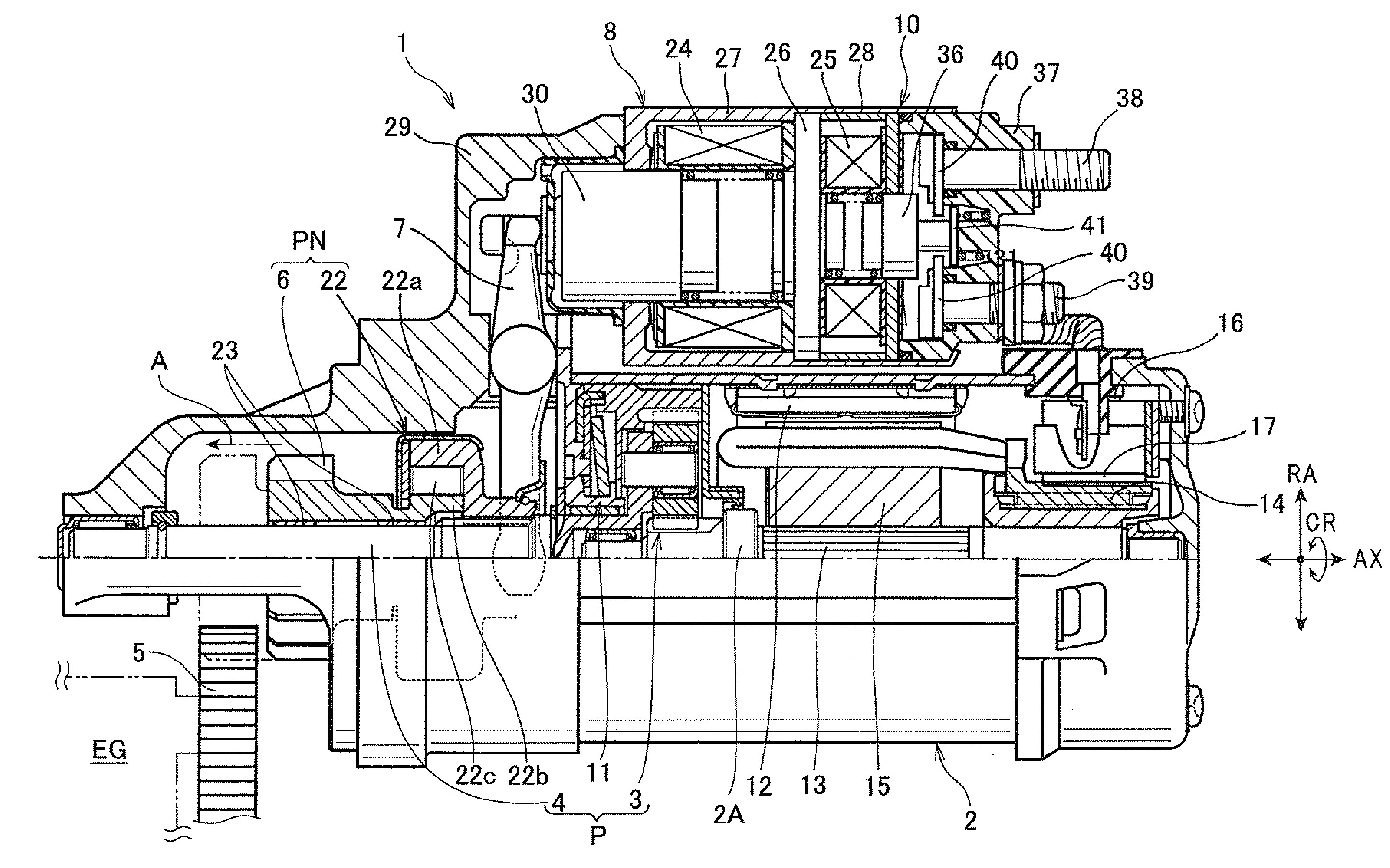
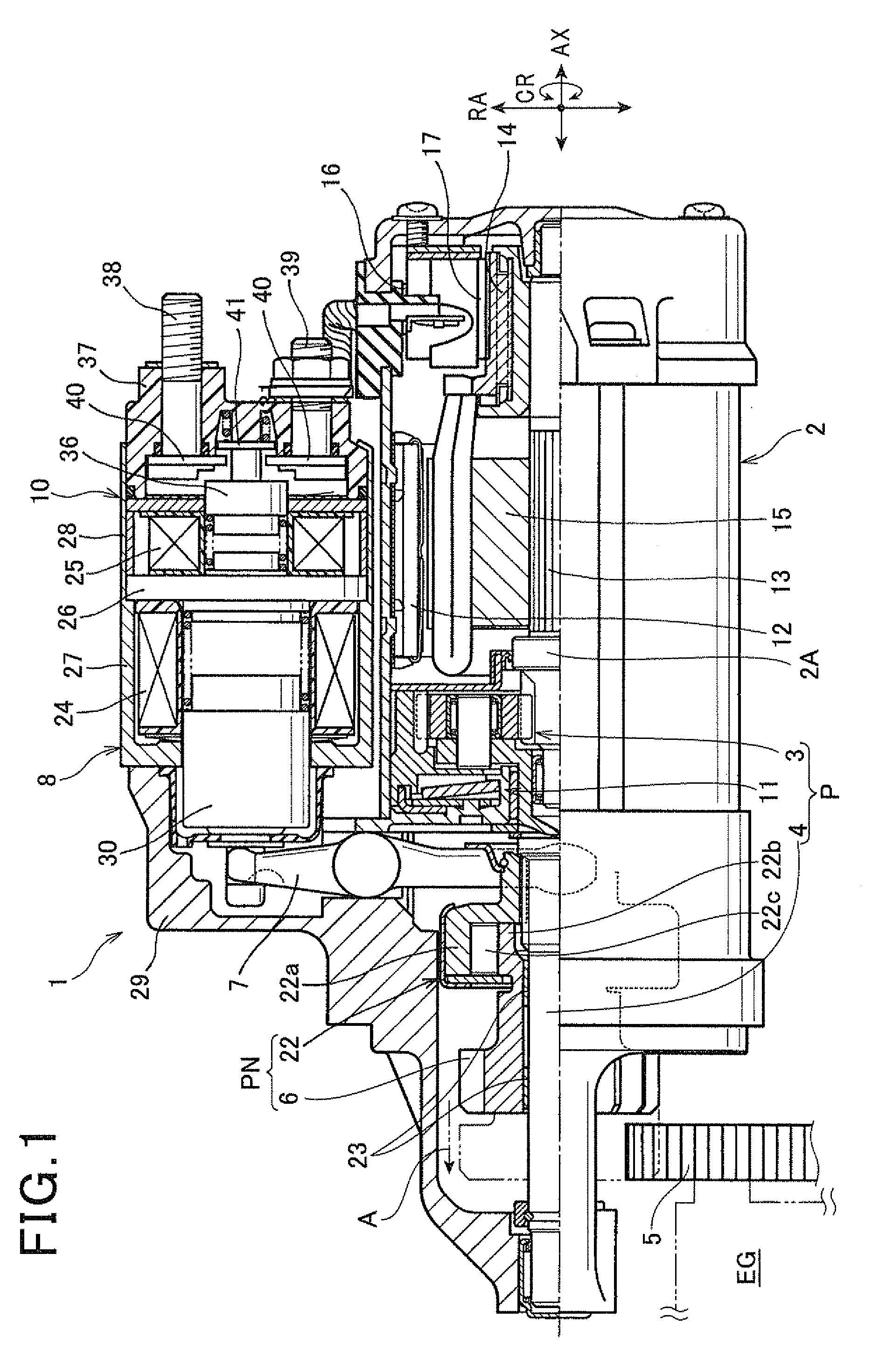
[0027]FIG. 1 shows an overall configuration of a starter 1 that starts an engine in a vehicle.

[0028]As shown in FIG. 1, the starter 1 according to the embodiment includes an electric motor 2 serving as a power source for driving an engine. The starter 1 also includes a speed reducer 3, an output shaft 4, a pinion movable body PN, a pinion-pushing solenoid 8, a motor current-supply switch 10, and a shock absorbing device 11. The pinion movable body PN includes a pinion 6 and a clutch 22. In addition, the longer direction of the starter 1 is the axial direction AX, the directions which are radially-perpendicular to the axial direction AX are radial direction RA, and the rotation direction centering on the axis of the longer direction is a circumferential direction CR.

[0029]The motor 2 receives power supplied from a power supply and rotates, ...


PUM


Abstract

A starter for starting an engine in a vehicle is disclosed. The starter includes a motor and an output shaft that rotates by receiving torque from the motor. The starter also includes a pinion movable body that includes a pinion for transmitting the torque of the motor to a ring gear of the engine. The pinion movable body is provided on an outer circumference of the output shaft integrally with the pinion in a manner allowing movement along an axial direction thereof. The pinion is pushed towards the ring gear by a pinion-pushing means. A motor current-supply means turns ON and OFF energizing current flowing to the motor. A shock absorbing device is disposed on a torque transmitting path transmitting the torque of the motor to the pinion.

Description

CROSS-REFERENCE TO RELATED APPLICATION[0001]This application is based on and claims the benefit of priority from earlier Japanese Patent Application No. 2009-109099 filed on Apr. 28, 2009, the description of which is incorporated herein by reference.BACKGROUND OF THE INVENTION[0002]1. Field of the Invention[0003]The present invention relates to a starter for starting an engine (internal combustion engine) in a vehicle and the like. In particular, the present invention relates to a so-called plunging-type starter in which a pinion and a ring gear of an engine mesh when the engine is started. The starter can be suitably used in a vehicle equipped with an engine stop / restart apparatus.[0004]2. Description of the Related Art[0005]From environmental considerations and the like, vehicles of recent years include an engine stop / restart apparatus (referred to, hereinafter, as an idle stop apparatus) that automatically controls stopping and restarting of an engine.[0006]As an example of the i...

Claims


Application Information

Patent Timeline
Patent Type & Authority Applications(United States)
IPC IPC(8): F02N15/06
CPCB60W10/06Y10T74/134B60W30/192F02N11/0844F02N11/0855F02N11/087F02N15/022F02N15/046F02N15/063F02N15/067F02N99/004F02N2300/2002H01H51/065Y02T10/48Y10T74/137Y10T74/131B60W10/08F02N15/025
Inventor NIIMI, MASAMIYOSHIDA, YASUYUKIMURATA, MITSUHIROHARUNO, KIYOKAZU
Owner DENSO CORP
Why Eureka
Try Eureka