Fluid cooled coupling assembly
- Summary
- Abstract
- Description
- Claims
- Application Information
AI Technical Summary
Benefits of technology
Problems solved by technology
Method used
Image

Examples
Embodiment Construction
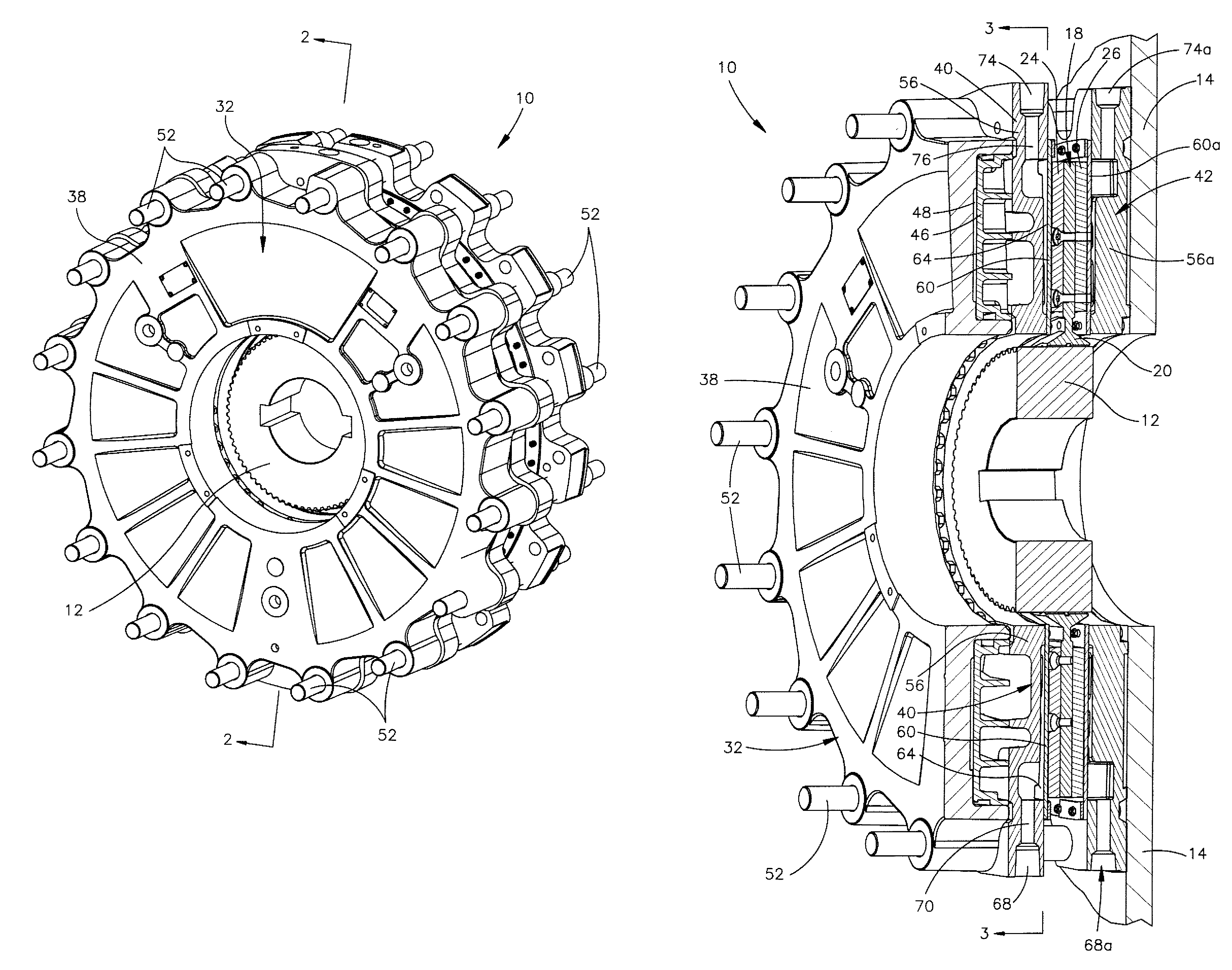
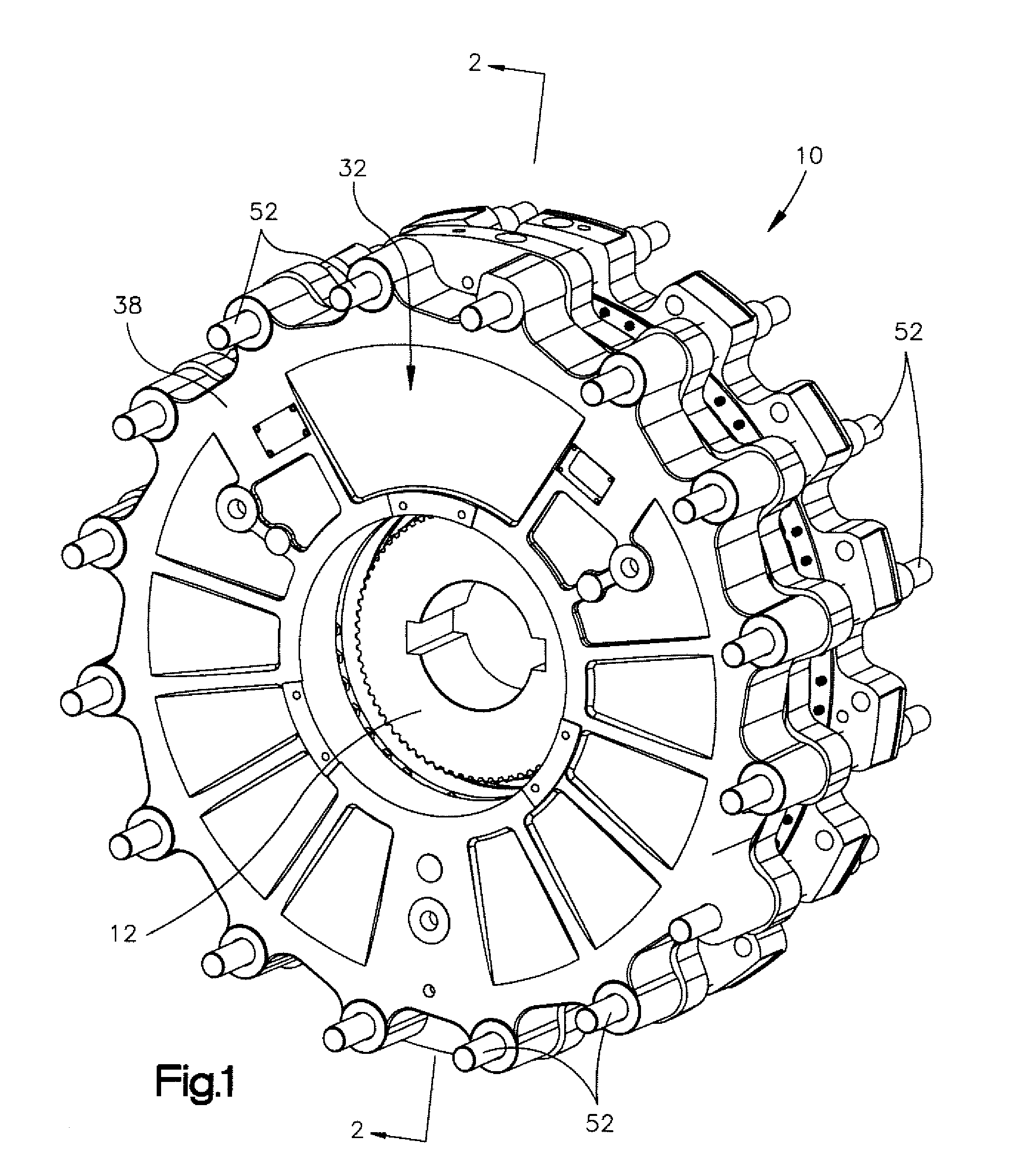
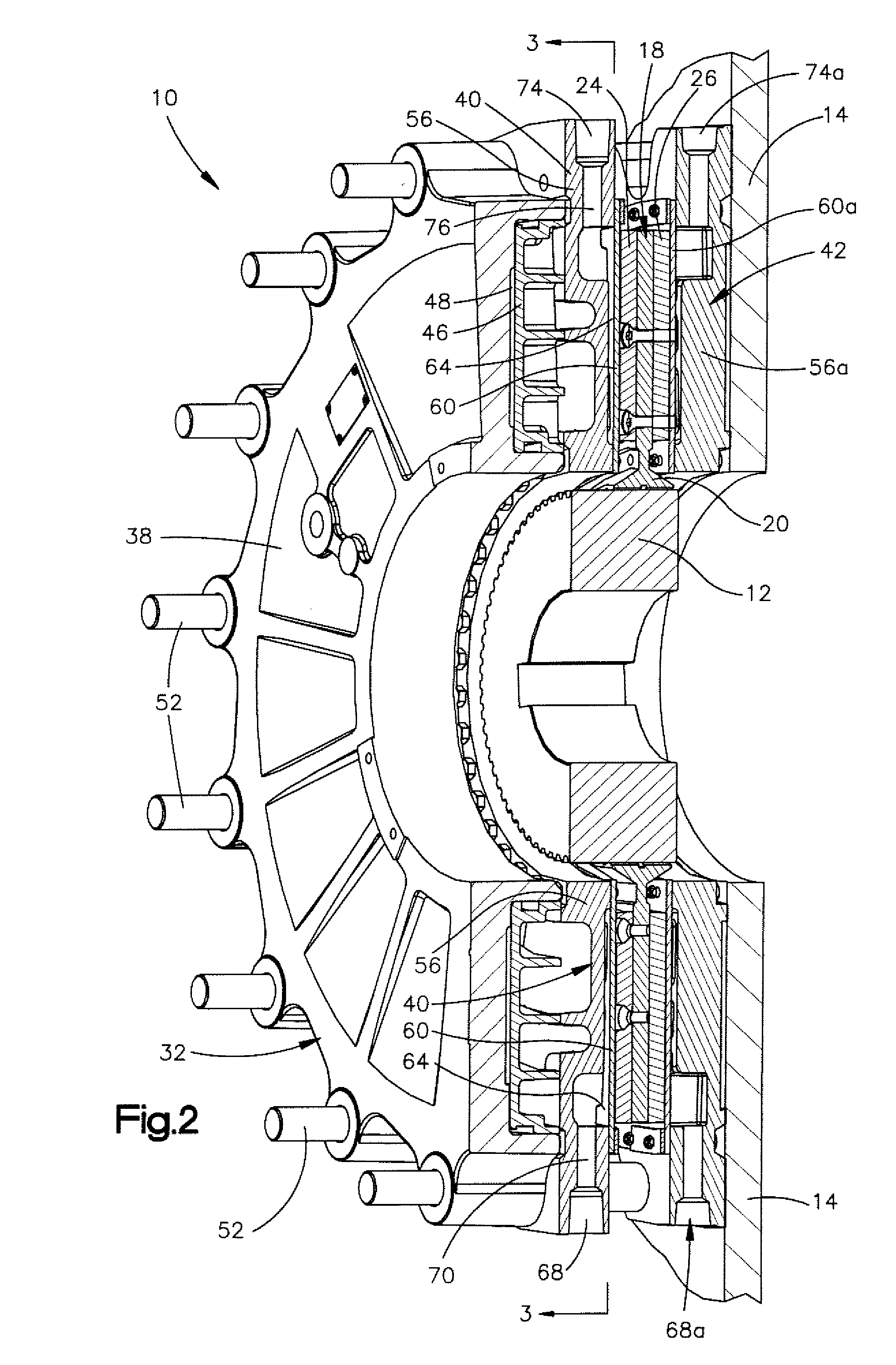
[0019]A coupling assembly 10 (FIGS. 1 and 2) is utilized to transmit force between a rotatable input member 12 and a stationary member 14 (FIG. 2). In the illustrated embodiment, the coupling assembly 10 is utilized as a brake and force is transmitted between the stationary member 14 and input member 12 by the coupling assembly 10 to hold the input member against rotation. If the coupling assembly 10 is to be utilized as a clutch, the member 14 would be rotatable under the influence of force transmitted from the input member 12 through the coupling assembly 10 to the member 14. It should be understood that the coupling assembly 10 may be a combination brake and clutch assembly.
[0020]The coupling assembly 10 (FIG. 2) includes a rotatable annular disc 18 to which the input member 12 is connected. In the illustrated embodiment, the input member 12 is a gear which is connected to a rotatable input shaft (not shown). A circular array of teeth on the periphery of the gear 12 are received ...
PUM
 Abstract
Description
Claims
Application Information
PatSnap Eureka turns technology decisions into work you can execute. Powered by our Innovation Knowledge Graph, it runs expert workflows across engineering, life sciences, materials and intellectual property. Get your review-ready output in minutes.


