Smart Electronic Switch for Low-Power Loads

a low-power load, electronic switch technology, applied in relays, safety/protection circuits, pulse techniques, etc., can solve problems such as problems such as electrical load not operating properly, electrical load not available all the time, and electrical load may not be suitable for some types of electrical load, and achieve small magnitude

Active Publication Date: 2010-10-28
LUTRON TECH CO LLC
View PDF23 Cites 137 Cited by
  • Summary
  • Abstract
  • Description
  • Claims
  • Application Information

AI Technical Summary

Benefits of technology

[0010]In addition, a power supply for an electronic switch that comprises a controllably conductive device adapted to be coupled between an AC power source and an electrical load for turning the electrical load on and off is also described herein. The electronic switch comprises an output capacitor operable to develop to a DC supply voltage, a bidirectional semiconductor switch adapted to be coupled in series with the controllably conductive device and in parallel with the output capacitor, and a control circuit coupled to the bidirectional semiconductor switch for rendering the bidirectional semiconductor switch conductive and non-conductive. The output capacitor is operable to charge when the bidirectional semiconductor switch is non-conductive. The control circuit is responsive to the magnitude of the DC supply voltage to render the bidirectional semiconductor switch conductive when the magnitude of the DC supply voltage reaches a maximum DC supply voltage threshold and to render the bidirectional semiconductor switch non-conductive when the magnitude of the DC supply voltage drops to a minimum DC supply voltage threshold. A voltage developed across the power supply when the output capacitor is charging has a substantially small magnitude as compared to a peak voltage of an AC line voltage of the AC power source when the output capacitor is charging. The power supply controls when the output capacitor charges asynchronously with respect to the frequency of the AC power source, such that the in-line power supply is to start and stop charging at any time during each half cycle. The power supply starts and stops charging the output capacitor at least once during each half cycle of the AC power source.

Problems solved by technology

As a result, not all of the AC line voltage of the AC power source is available to power the electrical load and the electrical load may not operate properly.
In addition, the power supply must draw current through the controlled electrical load in order to charge, which may cause problems for some types of electrical loads.
For example, when the electrical load is a lighting load, the magnitude of the power supply current must not be great enough to cause the lighting load to illuminate or to flicker.
Further, some electrical loads, such as compact fluorescent lamps, do not conduct sinusoidal currents, and as a result, current cannot be conducted through these electrical loads during certain portions of the line cycle of the AC power source.

Method used


Image

  • Smart Electronic Switch for Low-Power Loads
  • Smart Electronic Switch for Low-Power Loads
  • Smart Electronic Switch for Low-Power Loads

Examples


Embodiment Construction

[0028]The foregoing summary, as well as the following detailed description of the preferred embodiments, is better understood when read in conjunction with the appended drawings. For the purposes of illustrating the invention, there is shown in the drawings an embodiment that is presently preferred, in which like numerals represent similar parts throughout the several views of the drawings, it being understood, however, that the invention is not limited to the specific methods and instrumentalities disclosed.

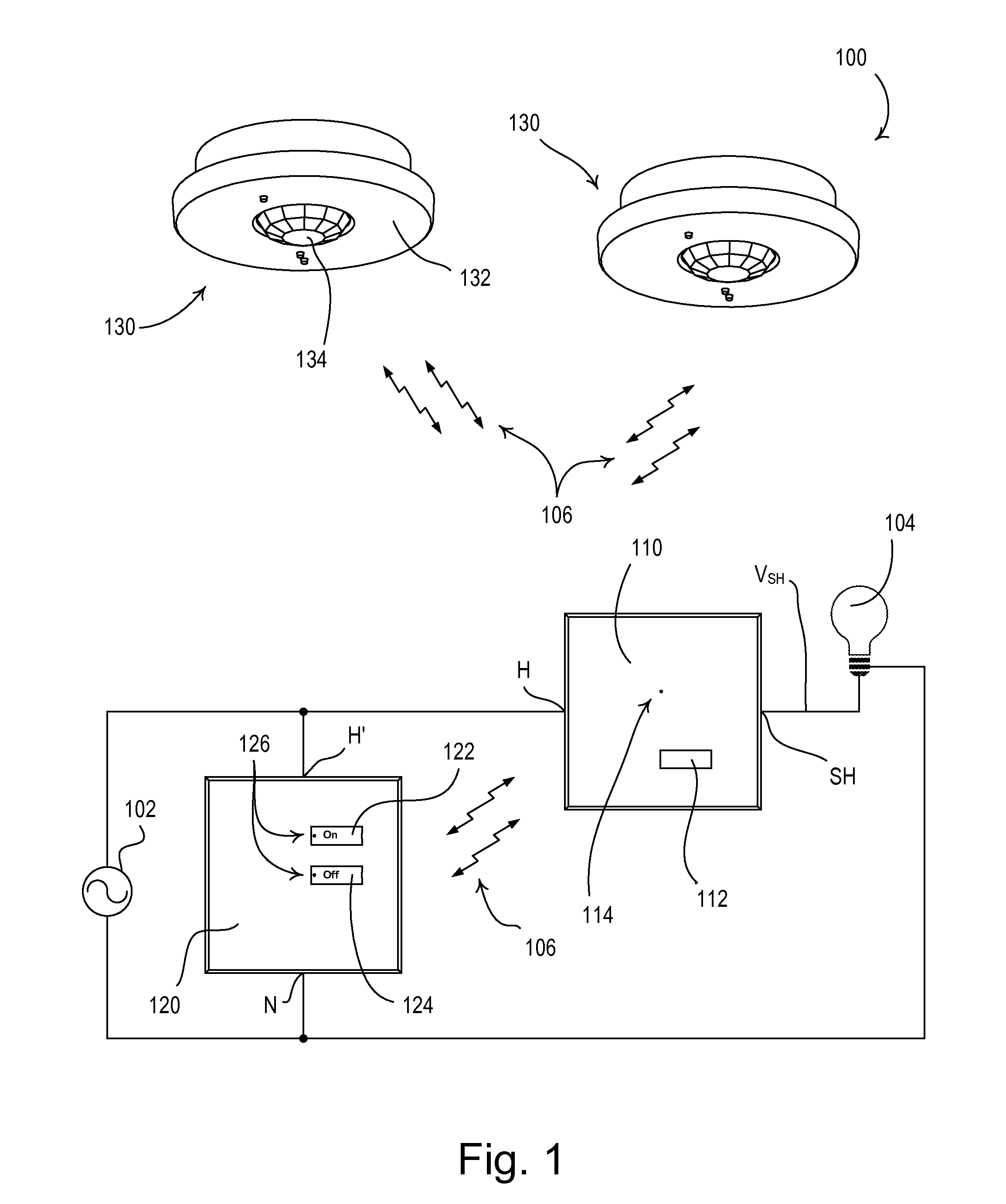
[0029]FIG. 1 is a simple diagram of a radio-frequency (RF) lighting control system 100 comprising a two-wire electronic switch 110, a keypad 120, and two remote occupancy sensors 130 according to a first embodiment of the present invention. The electronic switch 110 and the keypad 120 are adapted to be wall-mounted in standard electrical wallboxes. Alternatively, the electronic switch 110 and the keypad 120 could be implemented as table-top control devices. In addition, the elec...


PUM


Abstract

A two-wire smart load control device, such as an electronic switch, for controlling the power delivered from a power source to an electrical load comprises a relay for conducting a load current through the load and an in-line power supply coupled in series with the relay for generating a supply voltage across a capacitor when the relay is conductive. The power supply controls when the capacitor charges asynchronously with respect to the frequency of the source. The capacitor conducts the load current for at least a portion of a line cycle of the source when the relay is conductive. The load control device also comprises a bidirectional semiconductor switch, which is controlled to minimize the inrush current conducted through the relay. The bidirectional semiconductor switch is rendered conductive in response to an over-current condition in the capacitor of the power supply, and the relay is rendered non-conductive in response to an over-temperature condition in the power supply.

Description

CROSS-REFERENCE TO RELATED APPLICATIONS[0001]This application is a non-provisional application of commonly-assigned U.S. Provisional Application Ser. No. 61 / 172,511, filed Apr. 24, 2009, entitled SMART LOAD CONTROL DEVICE HAVING A ZERO-CURRENT OFF STATE, and U.S. Provisional Application Ser. No. 61 / 226,990, filed Jul. 20, 2009, entitled SMART ELECTRONIC SWITCH FOR LOW-POWER LOADS, the entire disclosures of which are hereby incorporated by reference.BACKGROUND OF THE INVENTION[0002]1. Field of the Invention[0003]The present invention relates to load control devices for control of the power delivered from an alternating-current (AC) power source to an electrical load, and more particularly, to a “smart” two-wire electronic switch having a controller, a latching relay, and a power supply that provides substantially all of the line voltage of the AC power source to the load and draws current through the load in a manner that does not result in inappropriate operation of the load.[0004]2...

Claims


Application Information

Patent Timeline
Patent Type & Authority Applications(United States)
IPC IPC(8): H02J7/00H02M1/00
CPCH02M5/293H02M2001/0006H03K17/6874H03K17/79H05B37/0218H02J7/0052H05B39/081H05B39/088Y02B20/46Y02B20/48H01H47/22H05B37/0227H05B47/11Y02B20/40H05B47/13H05B47/115H02M1/0006H02J7/0031H02J7/00H05B47/105
Inventor HAUSMAN, JR., DONALD F.AGUADO PELAEZ, MIGUELSALVESTRINI, CHRISTOPHER JAMESYANG, BINGRUI
Owner LUTRON TECH CO LLC
Why Eureka
Try Eureka